
- Standard Microsystems Super I/O with LPC Interface Data Sheet


64-Pin Super I/O with LPC Interface
SMSC LPC47N217N 64TQFP 5 Revision 0.2 (09-25-08)
PRODUCT PREVIEW
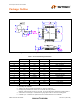
Package Outline
Notes:
1. Controlling Unit: millimeter.
2. Tolerance on the true position of the leads is ± 0.035 mm maximum.
3. Package body dimensions D1 and E1 do not include the mold protrusion.
Maximum mold protrusion is 0.25 mm per side. D1 and E1 dimensions determined at datum plane H.
4. 4 Dimension for foot length L measured at the gauge plane 0.25 mm above the seating plane.
5. 5 Details of pin 1 identifier are optional but must be located within the zone indicated.
Figure 2 64 Pin TQFP Package Outline, 7X7X1.4 Body, 2 MM Footprint
Table 1 64 Pin TQFP Package Parameters
MIN NOMINAL MAX REMARKS
A ~ ~ 1.60 Overall Package Height
A1 0.05 ~ 0.15 Standoff
A2 1.35 1.40 1.45 Body Thickness
D 8.80 9.00 9.20 X Span
D1 6.80 7.00 7.20 X body Size
E 8.80 9.00 9.20 Y Span
E1 6.80 7.00 7.20 Y body Size
H 0.09 ~ 0.20 Lead Frame Thickness
L 0.45 0.60 0.75 Lead Foot Length
L1 ~ 1.00 REF. ~ Lead Length
e 0.40 Basic Lead Pitch
0
o
~7
o
Lead Foot Angle
W 0.13 0.18 0.23 Lead Width
ccc ~ ~ 0.08 Coplanarity