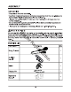
SNAPPER §, 48V Cordless String Trimmer 1696956 & 80075680 / ST Owner's Manual TOLL-FREE HELPLINE: 1-800-317-7833 Whippersnapper £ Read all safety rules and Instructions carefully before operating this tool.
CONTENTS CONSENT ...evening v sentence ens ran s n s salesmen e Specifications Important Safety Instructions Symbols Know Your String Trimmer, Assembly Operation . Maintenance . Environmentally Safe Battery Dipsos al.. Troubleshooting 28 .28 Exploded view. @, 30 Parts list. Cutting Width . Line .080" (2.0 mm) Speed 5/6300110% RPM FEE TYPE Bump Feed Weight (without battery’ ..6.8 bs (3.1 kg) Disclaimer: *Maximum initial battery collage (measured without a workload} is 48 volts. Nominal voltage is 43.
IMPORTANT SAFETY INSTRUCTIONS WARNING Read and understand all instructions before using this product. Failure to follow all instructions listed below may result in strict shock, fire, and for serious personal injury. «Use only identical manufacturer's replacement parks and accessories. Use of any other parts may create a hazard or cause product damage. « Always wear safely glasses with side shields marked {o comply with ANS! Z87.1. Everyday glasses have only impact resistant lenses.
IMPORTANT SAFETY INSTRUCTIONS mountings, and any other condition that may affect its operation. A guard or other part that is damaged should be properly repaired or replaced by an authorized service center unless indicated elsewhere in this manual. «Do not charge or operate cordless tools in damp or wet locations or in the rain. Following this rule will reduce the risk of electric shock. *Remove or disconnect battery before servicing, cleaning or removing material from the gardening appliance.
IMPORTANT SAFETY INSTRUCTIONS *Follow all charging instructions and do not charge the battery pack or appliance outside of the temperature range specified in the instructions. Charging improperly or at temperatures outside of the specified range may damage the battery and increase the risk of fire. »Have servicing performed by a qualified repair person using only identical replacement parts. This will ensure that the safety of the product is maintained. »Prevent unintentional starting.
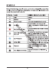
SYMBOLS Some of the following symbols may be used on this product. Please study them and learn their meaning. Proper interpretation of these symbols will allow you fo operate the product better and safer. SYMBOL | NAME DESIGNATION/EXPLANATION v Volts Voltage Minutes Time Direct Current Type or a characteristic of current Do not install or use any type of No awe blade on a product or displaying this %( symbol. Wet Condition fret Do not expose to rain or use in damp locations.
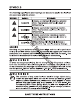
SYMBOLS The following signal words and meanings are intended fo explain the levels of risk associated with this product. SYMBOL SIGNAL MEANING Indicates an imminently hazardous situation, A | pang Er which, if not avoided, will resit in death or serious injury. n indicates a potentially hazardous situation, WARNING |which, if not avoided, could result in death or serious injury. A Indicates a potentially hazardous situation, which, if not avoided, may result in minor or moderate injury.
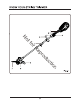
KNOW YOUR STRING TRIMMER KNOW YOUR STRING TRIMMER (See Figure 1) The safe use of this product requires an understanding of the information on the product and in this operator’s manual as well as a knowledge of the project you are attempting. Before use of this product, familiarize yourself with all operating features and safety rules. 1. REAR HANDLE Ergonomic handle with oversold improves comfort and grip. 2. SAFETY LOCK-KT TRIGGER The safety lock-outrigger prevents accidental starting. 3.
ASSEMBLY UNPACKING This product requires assembly. « Carefully remove the product and any accessories from the box. Make sure that all items listed in the packing list are included. = Inspect the tool carefully to make sirs no breakage or damage occurred during shipping. Do not discard the packing material until you have carefully inspected and satisfactorily operated the fool. »If any parts are damaged or missing, please call 1-800-317-7833.
ASSEMBLY WARNING If any parts are damaged or missing, do not operate this product until the pairs are replaced. Use of this product with damaged or missing parts could result in serious personal injury. WARNING Do not attempt to modify this product or create accessories not recommended for use with this string trimmer. Any such alteration or modification is misuse and could result in a hazardous condition leading to possible serious personal injury. Do not connect & er supply until assembly is complete.
ASSEMBLY ATTACH THE GUARD (See Figures 3.1 3.3} NOTE: Install the guard before the attachment is connected fo the Sower shaft. 1. Invert the string trimmer to access the trimmer head. 2. Remove)supplied screws (1) from the guard with a Philips screwdriver (not included). lots on the trimmer head. 4. Align the screw holes on #he guard (2) with the screw holes on the trimmer head (3). N 5. Insert the screws into the trimmer head, fastening the guard in place using a Philips head screwdriver {not included).
ASSEMBLY INSTALL THE UPPER SHAFT TO THE LOWER SHAFT (See Figures 4.1 and 4.2) HA WARNING Never install, remove, or adjust any attachment while siring grimmer is running. Failure to stop the motor can cause serious personal injury. The attachment connects to the power head by means of a couplet device. Set the unit on a flat, level surface. Loosen the knob (1) on the couplet (5. Push in the n button (2) located on the lower shaft (3).
ASSEMBLY ATTACH THE AUXILIARY HANDLE (See Figures 5.1 and 5.2) 1. Loosen the two screws (1) in the handle with a Philips screwdriver (not included) and remove the screws from the handle. 2. Alas the auxiliary handle d lower clamp (3} on the shaft. 3. Adjust handle up or down, if n chary, to desired operating position. Insert and tighten the two screws so that the handle cannot be rotated on the shaft.
ASSEMBLY ADJUST THE CUTTING SWATH (See Figure 6) This trimmer is equipped with a line cut-off blade on the guard. The line cut off blade continuously trims the line fo ensure a consistent and efficient cut diameter. Advance line whenever you hear the engine running Taster than normal, or when trimming efficiency diminishes. This will maintain best performance and keep line long enough to advance properly. This trimmer is currently set at the 11 in. cutting swath.
OPERATION WARNING Do not allow familiarity with this product to make you careless. Remember that a careless fraction of a second is sufficient to inflict serious injury. WARNING Do not use any attachments or accessories not recommended by the manufacturer of this product. The use of attachments or accessories not recommended can result in serious personal injury. WARNING This string trimmers not meant o be used with brush cutter attachments.
OPERATION INSTALLING THE BATTERY PACK (See Figure 7) = Align raised ribs on battery pack with grooves in the trimmer’s battery port. »Make sure the latch on the battery pack clicks into place and the battery pack is fully seated and secured in the trimmer before beginning operation. REMOVING THE BATTERY PACK (See Figure 7) « Depress the battery release button (1) in the back of the battery pack and pull the battery pack out of the tool.
OPERATION OPERATING THE TRIMMER (See Figure 9) WARNING Always hold the string trimmer away from the body keeping clearance between the body and the siring trimmer. Any contact with the string trimmer cutting head while operating can result in serious personal injury. Follow these tips when using the siring trimmer: « Hold the trimmer with your right hand on the rear handle and your left hand on the auxiliary handle. «Keep a firm grip with both hands while in operation.
OPERATION ADVANCING LINE (See Figure 10.) While the string trimmer is operating, the cutting line gels worn down and becomes shorter. This trimmer is equipped with bump feed line advancement, which advances additional line once the head is bumped on the ground while rotating. The cutting blade will cut the line to keep an accurate cutting swath. 1. Remove the battery p m the tool, 2. Press the tabs simultaneous the side of the trimmer head and remove cover and spool. SPOOL REPLACE W!See Figures 11.1 11.
OPERATION €. When installing new line on an existing spool, hold the spool as shown. 7. Bend the line at the midpoint and insert the bend info the slot in the center rim of the spool. Make sure that the line snaps into position in the slot. around the spool in & ise direction. 8.
OPERATION 10. Place the spool in the cover as shown below. 11. Insert the end 12. Reinstall the spool and cover onto the' snaps lino place.
OPERATION BUMP KNOB REPLACEMENT (See Figures 12.1 12.3) 1. Remove the battery pack. 2. Press the tabs simultaneously on the side of the trimmer head and remove cover and spool.
OPERATION CUTTING TIPS (See Figure 13) *Keep the trimmer lifted toward the area being cut; this is the best cutting area. * The trimmer cuts when passing the unit from right to left. This will avoid throwing debris at the operator. Avoid cutting in the dangerous area shown in figure 13. =Use the tip of string to do the cutting; do not force string head into uncut grass. = Wire and picket fences cause extra siring wear and breakage. Stone and brick walls, curbs, and wood may wear string rapidly.
MAINTENANCE GENERAL MAINTENANCE Avoid using solvents when cleaning plastic parts. Most plastics are susceptible to damage from various types of commercial solvents and may be damaged by their use. Use clean cloths to remove dirt, dust, lubricant, grease, sic. Always store the machine clean and in a dry enclosure with the battery charged.
ENVIRONMENTALLY SAFE BATTERY DISPOSAL The following toxic and corrosive materials are in the batteries used in this siring grimmer battery pack: Lithium-Lon, a toxic material. & WARNING All toxic materials must be disposed of in & specified manner {o prevent contamination of the environment. Before disposing of damaged or worn out Lithium-Lon battery hacks, contact your local waste disposal agency, or the local Environmental P on Agency for information and specific instructions.
TROUBLESHOOTING when trigger lock button is depressed. Problem Cause Solution 1. The battery pack 1. Attach the battery pack fo the is not attached to the trimmer. trimmer. Stein 2. No electrical contact |2. Remove battery check contact i g between the grimmer and|and reinstall the battery pack. mummer battery. falls to start : 3. The battery packs depleted. 3. Charge the battery pack. 4. The lock-out and trigger pressed 4.
TROUBLESHOOTING Problem Cause Solution 1. Lines are welded to 1. Lubricate with silicone spray. themselves. Re spool the head by following the directions in this manual. 2. Not enough line on |2. Install more line. Refer to Line ) . spool. Replacement earlier in this manual. not 3. Lines are womb foo 3. Manually advance the line by ’ short. pressing the bump knob. 4. Lines are tangled on 4. Remove lines from spool and spool. rewind. Refer to Line Replacement airier in this manual. 1. Tn sed 1.
LIMITED WARRANTY Briggs & Castration warrants that, during the warranty period specified below, it will repair or replace, free of charge, any part that is defective in material or workmanship or both. Transportation charges on product submitted for repair or replacement under this warranty must be bone by purchaser. This warranty is effective for and is subject o the time periods and conditions stated below. For warranty service, find the nearest Authorized Service Dealer in our dealer locator map at www.
LIMITED WARRANTY To ensure prompt and complete warranty coverage, register your product at the website shown above or at www.onlineproductregisiration.com. Save your proof of purchase receipt. If you do not provide proof of the initial purchase date atf the time warranty service is requested, the manufacturing date of the product will be used o determine the warranty period. Product registration is not required to obtain warranty service on Briggs & Castration products.