OPERATOR’S MANUAL 42” Angling Snow / Dozer Blade & Hitch Snow Plow/Dozer Blade Mfg. No. 1693754 Description 42” Angling Dozer Blade (Multiple Applications) Hitch Mfg. No.
Table of Contents Adjustments.........................................................7 Skid Shoe Adjustment .....................................7 Spring Tension.................................................7 Lift Rod Adjustment .........................................8 Downward Pressure Adjustment .....................8 Recommended Accessories ..............................1 Safety Rules & Information General Warnings............................................2 Operating on Slopes...................
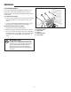
Safety Rules & Information Read these safety rules and follow them closely. Failure to obey these rules could result in loss of control of unit, severe personal injury or death to you, or bystanders, or damage to property or equipment. The triangle in text signifies important cautions or warnings which must be followed. PREPARATION GENERAL WARNINGS ● Disengage the PTO before making any adjustments. ● Never attempt to make any adjustments while engine is running.
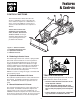
Features & Controls CONTROL FUNCTIONS B C A The information below briefly describes the function of individual controls. Operating the tractor and dozer require the combined use of these controls and additional controls whose operation is described in the tractor Operator’s Manual. Please take a moment and familiarize yourself with the name, location, and function of these controls so that you will better understand the safety and operating instructions provided in this manual. Figure 1.
General Operating Instructions Checks Before Starting WARNING 1. Refer to the Maintenance & Adjustments sections of this manual and perform any needed service. Also, refer to the tractor Operator’s Manual and perform any required service. Perform the Safety System Interlock test found in your tractor Operator’s Manual. If tractor does not pass the test, do not operate the tractor. See your authorized dealer. Under no circumstances should you attempt to defeat the safety system. 2.
General Operating Instructions Changing Angle of the Blade: Snow Plowing Tips See Figure 1 for location of Controls. • Determine the best snow removal pattern before beginning. NOTE: It is easier to change the angle of the blade with the attachment raised. • Plan the pattern so that you avoid pushing snow onto cleared areas. 1. Raise the attachment lift. • When land contour permits, it is best to travel in long straight lines to minimize turning. 2.
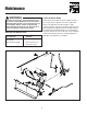
Maintenance WARNING Lubricate Dozer Blade To avoid serious injury, perform maintenance on the tractor or dozer blade only when the engine is stopped, parking brake is set and all moving parts have stopped. Always remove the ignition key before beginning maintenance or adjustments to prevent accidental starting of the engine. Lubricate the dozer blade as shown in Figure 2. Where an oil can is shown, wipe the area clean, apply a few drops of oil (SAE 30), then wipe up drips or spills.
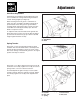
Adjustments Skid Shoe Adjustment Slotted holes are provided to permit adjustment of the shoe assemblies for raising and lowering the blade to various working heights (see Figure 3). When cleaning snow from gravel or earth drives or walks, the shoe assemblies should be lowered fully to prevent blade contact with gravel or ground. When cleaning smooth hard surfaces like concrete, the shoe assemblies are normally placed fully up to allow the blade to scrape the surface.
Adjustments Lift Rod Adjustment In the fully raised position the blade should be 4”-5” off the ground. In the fully lowered position, the lift rod should compress the spring creating downward pressure on the blade. D C B LIFT HEIGHT ADJUSTMENT A 1. Fully raise the attachment lift. The attachment should be approximately 4”-5” off the ground. If not, go to step 2. 2. Lower the attachment and adjust the front set collar (A, Figure 6) to achieve the correct lift height. E DOWNWARD PRESSURE ADJUSTMENT 1.
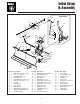
Initial Setup & Assembly Pivot Hitch 30 1 31 4 5 4 6 38 3 32 4 2 4 33 3 7 8 9 10 29 28 35 11 12 37 34 36 27 2 26 25 22 24 23 10 21 20 17 18 19 15 13 14 Ref Qty Description 1 1 ROD, Control Handle, Upper 2 6 NUT, Hex, 5/16-18 3 2 LOCKWASHER, 5/16 4 4 WASHER, 5/16 5 2 CAPSCREW, 5/16-18 x 1-1/4 6 1 ROD, Control Handle, Lower 7 1 CLEVIS 8 1 WASHER, 1/2 9 1 CLIP, Hair Pin 10 3 COTTER PIN 11 1 ROD & PLATE ASMY, Pivot 12 1 DOZER BLADE ASMY, 42” 13 1 SCRAPER BAR 15 16 Ref Qty Descri
Initial Setup & Assembly A D B Figure 8. Tension Springs A. Eyebolt B. Nut, 5/16 C. Spring C Figure 9. Install pivot hitch Assembly A. Safety Clip C. Long Hitch Pin B. Pivot Hitch D. Sub-Frame Hitch D. Pivot Frame E. Nut, 5/16 INITIAL SETUP & ASSEMBLY C Assemble Blade 1. See Figure 8. Insert threaded end of eyebolt (A) through lug on blade, and screw on 5/16 nut (B) just far enough so that it is flush with the end of the eyebolt. 2. See Figure 8. Hook the springs (C) into the pivot frame (D).
Initial Setup & Assembly Install Lift Rod 1. Insert the end of the rod guide (A, Figure 11) through hole in upright of lift arm (B), and secure with spring clip (C). C B NOTE: The rod guide (A, Figure 11) should be installed in the lower hole for hydraulic lift applications. For manual lift applications, the rod guide may be installed in either hole. The upper hole provides reduced lift effort; the lower hole provides increased lift height. A Figure 11. Lift Rod Assembly A. Rod Guide B.
Initial Setup & Assembly Install Angling Control Rod NOTE: If installing dozer blade on the unit equipped with a snowcab, the angling rod support (A, Figure 14) is not required. F B A 1. Remove the front two ratchet fasteners from the right foot rest pad. Peel the foot rest pad back. E 2. Remove and discard the taptite screw (F). 3. Mount the angling control rod support (A) to the bottom of the frame foot rest support (D). Secure using two 1/16-18 x 1 capscrews, washers, and nuts (C).
Removing & Attaching the Hitch & Blade A B B C D E B Figure 15. Dozer Removal A. Support Arm C. Pivot Pin B. Hair Pin Clip D. Hair Pin Clip & Washer E E. Hitch Pin & Safety Clip F. Pivot Hitch REMOVAL & INSTALLATION Removing & Attaching Dozer Blade 5. Lower the lift and remove the clip (B) securing the lift rod to the push bar and lift rod. 1. Lower the blade. Position the lift so that it is not lifting the blade or applying downward pressure. 6.
Lift Variations Snowthrower & Dozer Applications Snowthrower & Dozer Applications E A A B F C D E C B D Mower Applications Mower Applications G A A B F G F E Figure 16. Lift Lock Plate - Hydraulic Lift Models A. Lift Cylinder B. Flat Head Pin (Original) C. Flat Head Pin (New) D. Lock Plate E. Hair Pin Clips F. Lift Shaft Assy. G. Washers C D Figure 17. Lift Link - Manual Lift Models A. Pin B. Rear Hole of Lift Bar (Snowthrower Applications) C. Spacer D. Hair Pin Clip E.
Notes 15
Hardware Identification & Torque Specifications Common Hardware Types Torque Specification Chart Hex Head Capscrew FOR STANDARD MACHINE HARDWARE (Tolerance ± 20%) Washer Hardware Grade Lockwasher Carriage Bolt No Marks SAE Grade 2 Hex Nut Size Of Hardware Standard Hardware Sizing 8-32 8-36 10-24 10-32 1/4-20 1/4-28 5/16-18 5/16-24 3/8-16 3/8-24 7/16-14 7/16-20 1/2-13 1/2-20 9/16-12 9/16-18 5/8-11 5/8-18 3/4-10 3/4-16 7/8-9 7/8-14 1-8 1-12 When a washer or nut is identified as 1/2”, this is the
MANUFACTURING, INC. 500 N Spring Street / PO Box 997 Port Washington, WI 53074-0997 www.simplicitymfg.com © Copyright 2001 Simplicity Manufacturing, Inc. All Rights Reserved. Printed in USA.