n N ot fo rR ep ro du ct io 82V CORDLESS CHAIN SAW 1696773 (SXDCS82) Owner’s Manual TOLL-FREE hELPLinE: 1-800-317-7833 www.snapper.com Read all safety rules and instructions carefully before operating this tool.
CONTENTS Contents............................................................................................................................... 2 Product specifications........................................................................................................... 2 Important safety instructions................................................................................................ 3 Symbols..................................................................................................
Important safety instructions WA R NIN G Read and understand all instructions before using this product. Failure to follow all instructions listed below may result in electric shock, fire, and/or serious personal injury. Save all warnings and instructions for future reference. WORK AREA SAFETY Keep work area clean and well lit. Cluttered or dark areas invite accidents. • Do not operate Power tool in explosive atmospheres, such as in the presence of flammable liquids, gases, or dust.
important safety instructions POWER TOOL USE AND CARE Do not force the Power tool. Use the correct chainsaw for your application. The correct chainsaw will do the job better and safer at the rate for which it was designed. • Do not use the chainsaw if the switch does not turn it on and off. Any chainsaw that cannot be controlled with the switch is dangerous and must be repaired.
important safety instructions CHAIN SAW SAFETY WARNINGS Keep all parts of the body away from the saw chain when the chain saw is operation. Before you start the chain saw, make sure the saw chain is not contacting anything. A moment of inattention while operating chain saws may cause entanglement of your clothing or body with the saw chain. • Always hold the chain saw with your right hand on the rear handle and your left hand on the front handle.
important safety instructions WA R NIN G When using an cordless chainsaw, basic safety precaution should always be followed to reduce the risk of fire, electric shock, and injury to persons. WA R NIN G (PROPOSITION 65) n This product contains a chemical known to the state of California to cause cancer, birth defectsor other reproductive harm.
important safety instructions WA R NIN G ro du ct io n Kickback may occur when the moving chain contacts an object at the upper portion of the tip of the guide bar or when the wood closes in and pinches the saw chain in the cut. Contact at the upper portion of the tip of the guide bar can cause the chain to dig into the object and stop the chain for an instant. The result is a lightning fast reverse reaction which kicks the guide bar up and back toward the operator.
important safety instructions ro du ct io n Push and pull - This reaction force is always opposite to the direction the chain is moving where wood contact is made. Thus, the operator must be ready to control the PULL when cutting on the bottom edge of the bar, and PUSH when cutting along the top edge.
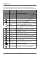
SymbolS Some of the following symbols may be used on this product. Please study them and learn their meaning. Proper interpretation of these symbols will allow you to operate the product better and safer. EXPLANATION Voltage. Current. Frequency(cycles per second) Power Time. Rotational speed, at no load Revolutions, strokes, surface speed, orbits etc.
SymbolS The following signal words and meanings are intended to explain the levels of risk associated with this product. SYMBOL SIGNAL MEANING Indicates an imminently hazardous situation, which, if not avoided, will result in death or serious injury. WARNING Indicates a potentially hazardous situation, which, if not avoided, could result in death or serious injury. CAUTION Indicates a potentially hazardous situation, which, if not avoided, may result in minor or moderate injury.
know your CHAIN SAW KNOW YOUR CHAIN SAW The safe use of this product requires an understanding of the information on the product and in this operator’s manual as well as a knowledge of the project you are attempting. Before use of this product, familiarize yourself with all operating features and safety rules.
ASSEMBLY UNPACKING This product has been shipped completely assembled. Carefully remove the product and any accessories from the box. Make sure that all items listed in the package contents section are included. • Inspect the product carefully to make sure no breakage or damage occurred during shipping. • Do not discard the packing material until you have carefully inspected and satisfactorily operated the product. • If any parts are damaged or missing, please call 1-800-317-7833 for assistance.
ASSEMBLY WA R NIN G Do not insert the battery until assembly is complete. Failure to comply could result in accidental starting and possible serious personal injury. ADDING BAR AND CHAIN LUBRICANT ro du ct io n Use a bar and chain lubricant with this product. It is designed for chains and chain oilers, and is formulated to perform over a wide temperature range with no dilution required. • Remove oil cap. • Carefully pour the bar and chain oil into the tank. • Wipe off excess oil and replace cap.
ASSEMBLY BATTERY I M P O R T AN T n The battery pack is not charged when it is purchased. Before using the chain saw for the first time, place the battery pack in the battery charger and charge it fully. Be sure to read all safety precautions, and follow the instructions in the section entitled Charging Procedure. With regular use, the battery will require shorter charging times. When storing the chain saw for a prolonged period of time, remove the battery.
ASSEMBLY TO REMOVE THE BATTERY: 1. rR ep ro du ct io n 2. Press the battery release button on the chain saw. This will cause the battery to raise out of the tool slightly. Grasp the chain saw firmly and pull the battery out of the handle. WA R NIN G N ot fo Follow these instructions in order to avoid injury and to reduce the risk of electric shock or fire: Replace the battery or the charger immediately if the battery case or charger cord is • damaged.
OPERATIon STARTING AND STOPPING THE CHAIN SAW ro du ct io n A. To start the chain saw: • Make sure chain tension is at desired setting. Refer to adjusting the chain tension in the Care and Maintenance section of this manual. • Make sure the chain cover lock knob is tight to the chain cover. • Make sure no objects or obstructions are in the immediate vicinity which could come in contact with the bar and chain. • Fit the battery into the chain saw. • Press the power button on the left of the rear handle.
OPERATIon OPERATING THE CHAIN BRAKE Check the operating condition of the chain brake prior to each use. • Engage the chain brake by rotating your left wrist towards the guard, allowing the back of your hand to engage the brake while the chain is rotating. Be sure to maintain both hands on the saw handles at all times.
OPERATIon PREPARING FOR CUTTING PROPER GRIP ON HANDLES See General Safety Rules for appropriate safety equipment. • Wear non-slip gloves for maximum grip and protection. Hold the saw firmly with both hands. Always keep your left hand on the front handle and your right hand on the rear handle so that your body is to the left of the chain line. • Maintain a proper grip on the saw whenever the motor is running. The fingers should encircle the handle and the thumb should be wrapped under the handlebar.
OPERATIon PROPER CUTTING STANCE • • • • Balance your weight with both feet on solid ground. Keep left arm with elbow locked in a “straight arm” position to withstand any kickback force. Keep your body to the left of the chain line. Keep your thumb on underside of front handle.
OPERATIon REMOVING BUTTRESS ROOTS Vertical Cut ro du ct io Planned Line of fall n A buttress root is a large root extending from the trunk of the tree above the ground. Remove large buttress roots prior to felling. Make the horizontal cut into the buttress first, followed by the vertical cut. Remove the resulting loose section from the work area. Follow the correct tree felling procedure as stated in Proper Procedure For Tree Felling after you have removed the large buttress roots.
OPERATIon • • ro du ct io n • Felling Backcut. As the felling cut gets close to the hinge, the tree should begin to fall. If there is any chance the tree may not fall in the desired direction or it may rock back and bind the saw chain, stop cutting before the felling cut is complete and use wedges of wood, plastic or aluminum to open the cut and drop the tree along its desired line of fall. Make the backcut level and horizontal, and at a minimum of 2 in. (5 cm) above the horizontal cut of the notch.
OPERATIon Bucking rR ep Kickback ro du ct io n Bucking is the term used for cutting a fallen tree to the desired log length. • Always make sure your footing is secure and your weight is distributed evenly on both feet. • Cut only one log at a time. • Support small logs on a saw horse or another log while bucking. • Keep a clear cutting area. Make sure that no objects can contact the guide bar nose and chain during cutting as this can cause kickback. Refer to Kickback earlier in this manual.
OPERATIon Bucking logs under stress When the log is supported on one end, cut 1/3 the diameter from the underside. Then make the finished cut by overbucking to meet the first cut. When the log is supported on both ends, cut 1/3 of the diameter from the top overback. Then make the finished cut by under bucking the lower 2/3 to meet the first cut.
OPERATIon Limbing n Limbing is removing branches from a fallen tree. • Work slowly, keeping both hands on the chain saw with a firm grip. Always make sure your footing is secure and your weight is distributed evenly on both feet. • Leave the larger support limbs under the tree to keep the tree off the ground while cutting. • Limbs should be cut one at a time. Remove the cut limbs from the work area often to help. • Keep the work area clean and safe.
OPERATIon Cutting springpoles SPRINGPOLE WA R NIN G ro du ct io n A springpole is any log, branch, rooted stump, or sapling which is bent under tension by other wood so that it springs back if the wood holding it is cut or removed. On a fallen tree, a rooted stump has a high potential of springing back to the upright position during the bucking cut to separate the log from the stump. Watch out for springpoles — they are dangerous.
Battery & Charger MAINTENANCE CHARGING PROCEDURE NOTE: The battery is not shipped fully charged. It is recommended to fully charge before first use to ensure that maximum run time can be achieved. This lithium-ion battery will not develop a memory and may be charged at any time. Low voltage charging: n If the battery has been stored with little to no charge for a long period of time, the charger will go into recovery mode, which will take 20 hrs to fully charge the battery.
BATTERY & CHARGER MAINTENANCE CHARGER MOUNTING This charger can be installed hanging on a wall using two #8 screws (not included). 2. Locate the placement for the charger to be wall mounted. 3. If fastening to wood studs use 2 wood screws (not included). 4. Drill two holes 4.5 in. apart ensuring that they are vertically aligned. 5. If fastening to drywall use wall anchors (not included) and screws to secure the charger to the wall. n 1.
MAINTENANCE General maintenance Avoid using solvents when cleaning plastic parts. Most plastics are susceptible to damage from various types of commercial solvents and may be damaged by their use. Use clean cloths to remove dirt, dust, lubricant, grease, etc., firmly to maintain control. LUBRICATION ro du ct io n All of the bearings in this product are lubricated with a sufficient amount of high grade lubricant for the life of the unit under normal operating conditions.
MAINTENANCE • • • Remove the battery from the chain saw. Remove the supplied wrench from the rear handle. Remove the two chain cover lock nuts from the chain cover by rotating them counterclockwise with the wrench. • • Remove the chain cover from the mounting surface. The bar and chain can now be removed by lifting it away from the main body of the saw and releasing the chain from the sprocket. Remove the old chain from the bar.
MAINTENANCE NOTE: Make certain of direction of the chain. • Position the chain so there is a loop at the back of the bar. • Hold the chain in position on the bar and place the loop around the sprocket. • fit the bar flush against the mounting surface so that the bar studs are in the long slot of the bar. Ensure that the chain is over the sprocket. • rR • Lift the tip of the guide bar up to check for sag. Release the tip of the guide bar and turn the chain adjustment screw 1/2 turn clockwise.
MAINTENANCE ADJUSTING THE CHAIN TENSION WA R NIN G Never touch or adjust the chain while the motor is running. The saw chain is very sharp. Always wear protective gloves when performing maintenance on the chain. n Nut Rotate the chain adjustment screw clockwise to increase the chain tension and rotate counterclockwise to decrease the chain tension. Once the chain is at the desired tension, tighten the chain cover lock nuts.
MAINTENANCE CHAIN MAINTENANCE ro du ct io n Use only a low-kickback chain on this saw. This fast-cutting chain provides kickback reduction when properly maintained. For smooth and fast cutting, maintain the chain properly. The chain requires sharpening when the wood chips are small and powdery, the chain must be forced through the wood during cutting, or the chain cuts to one side.
MAINTENANCE Sharpening the cutters • n • • • • ro du ct io • • Be careful to file all cutters to the specified angles and to the same length, as fast cutting can be obtained only when all cutters are uniform. Tension the chain prior to sharpening. Refer to Adjusting The Chain Tension. Use a 5/32 in. (4 mm) diameter round file and holder. Do all of your filing at the midpoint of the bar. Keep the file level with a top plate of the tooth. Do not let the file dip or rock. Using light but firm pressure.
MAINTENANCE TOP PLATE FILING ANGLE • CORRECT 30° – file holders are marked with guide marks to align file properly to produce correct top plate angle. • • LESS THAN 30° – for cross cutting. MORE THAN 30° – feathered edge dulls quickly. Side Plate Filling Angle Correct ro du ct io n Top Place Filling Angle Incorrect Hook rR ep Backward Slope Raker (Depth Gauge) Clearance 1/32” (0.
MAINTENANCE SIDE PLATE ANGLE • • n • • Maintain the depth gauge at a clearance of 1/32 in. (0.6 mm). Use a depth gauge tool for checking the depth gauge clearances. Every time the chain is filed, check the depth gauge clearance. Use a flat file and a depth gauge jointer to lower all gauges uniformly. Use a 1/32 in. (0.6 mm) depth gauge jointer. After lowering each depth gauge, restore original shape by rounding the front. Be careful not to damage adjoining drive links with the edge of the file.
MAINTENANCE QUICK REFERENCE OF CHAIN&BAR ASSEMBLY (CHAIN TENSION) wrench nut 2. Then loosen the adjustment screw 2 or 3 turns. 3. Now totally remove the chain cover lock nuts and remove the chain cover. ro du ct io 1. To remove the chain cover, loosen the two chain cover lock nuts by turning them counterclockwise with the supplied wrench. n wrench ep 4. The bar and chain can now be removed 5.
ENVIRONMENTALLY SAFE BATTERY DISPOSAL The following toxic and corrosive materials are in the batteries used in this chainsaw battery pack: Lithium-Ion, a toxic material. n WA R NIN G WA R NIN G ro du ct io All toxic materials must be disposed of in a specified manner to prevent contamination of the environment.
troubleshooting PROBLEM POSSIBLE Bar and chain running Check chain tension for hot and smoking. overtightened condition. SOLUTION Loosen the chain if it is too tight. Refer to Adjusting the Chain Tension earlier in this manual. Chain oil tank empty. Check oil tank. Refer to Chain Tension Guide earlier in this manual. Check guide bar and chain assembly. Refer to Replacing the Bar and Chain earlier in this manual. n motor runs, but chain Chain tension too tight. is not rotating. Dull chain.
LIMITED WARRANTY Briggs & Stratton warrants that, during the warranty period specified below, it will repair or replace, free of charge, any part that is defective in material or workmanship or both. Transportation charges on product submitted for repair or replacement under this warranty must be borne by purchaser. This warranty is effective for and is subject to the time periods and conditions stated below. For warranty service, find the nearest Authorized Service Dealer in our dealer locator map at www.
LIMITED WARRANTY ABOUT YOUR WARRANTY Warranty service is available only through Snapper Authorized Service Dealers. This warranty covers only defects in materials or workmanship. It does not cover damage caused by improper use or abuse, improper maintenance or repair, normal wear and tear, or stale or unapproved fuel. ro du ct io n Improper Use and Abuse - The proper, intended use of this product is described in the Operator’s Manual.
EXPLODED VIEW A A A A A A A ro du ct io n A A A AA A A A ep A A A A rR A A fo A ot A N A A A 109A 108A 41 A A
parts list Item No. Part No.
parts list Description fo N SWITCH, SIGNAL PCB SCREW KIT, TOP COVER ASSEMBLY,NA SCREW COVER, TOP SCREEN, DUST KIT, PCB, FOR STARTING KIT, INPUT TUBE ASSEMBLY SPRING TUBE,INPUT KIT, OIL TANK ASSEMBLY O-RING, SEAL TANK, OIL KIT, OIL TANK CAP ASSEMBLY STRAP, OIL CAP O-RING, SEAL ELEMENT, FILTER CAP, OIL TANK KIT, LEFT HOUSING ASSEMBLY, NA BUTTON HOUSING, LEFT NUT SCREW SCREW BRACKET, STABALIZER KIT, MOTOR COVER ASSEMBLY, NA SCREW SCREW COVER, MOTOR KIT, MOTOR ASSEMBLY, NA MOTOR CHANNEL, AIR OUTLET HOUSING,
parts list Description fo QTY 1 1 1 1 2 1 1 2 1 1 1 1 1 2 1 1 1 1 1 1 1 1 4 1 1 1 1 n SHAFT BEARING KIT, OIL VALVE ASSEMBLY ASSEMBLY, OIL VALVE SCREW KIT, FRONT HAND GUARD ASSEMBLY SPRING, TORSION SCREW BUSHING HANDGUARD,FRONT BUSHING KIT, BUMPER SPIKE ASSEMBLY BRACKET, BUMPER SPIKED SCREW KIT, CHAIN BLOCK DEVICE ASSEMBLY BRACKET, CHAIN BLOCK DEVICE SCREW KIT, OUTLET TUBE KIT, BAR COVER, NA & EU KIT, BAR, NA & EU KIT, SAW CHAIN KIT, FRONT HANDLE ASSEMBLY SCREW HANDLE, FRONT SHEATH BATTERY, 2AH, NA (OPTI
n ro du ct io ep rR fo ot N Briggs & Stratton Power Products Group, LLC P.O.
n ro du ct io N ot fo rR ep TRONÇONNEUSE SANS FIL 82 V 1696773 (SXDCS82) Guide d’utilisation SERVICE D’ASSISTANCE TÉLÉPHONIQUE SANS FRAIS: 1-800-317-7833 www.snapper.com Lisez toutes les règles de sécurité et toutes les instructions attentivement avant d’utiliser cet outil.
Matières Matières................................................................................................................................ 2 Fiche technique.................................................................................................................... 2 Consignes de sécurité.......................................................................................................... 3 Symboles............................................................................................
Consignes de sécurité AVERTISSEMENT Lisez les mises en garde et les instructions dans leur intégralité. Le non-respect des mises en garde et des instructions peut être à l’origine d’électrocutions, d’incendies et/ou de blessures graves. VEUILLEZ LIRE TOUTES LES CONSIGNES. La zone de travail doit être maintenue propre et bien rangée. Une zone de travail en désordre ou mal éclairée augmente les risques d’accident.
Consignes de sécurité Une tronçonneuse ne doit pas être utilisée dans un arbre. L’utilisation d’une tronçonneuse dans un arbre peut être à l’origine de blessures corporelles. • Habillez-vous de manière appropriée. Ne portez pas de vêtements amples ni de bijoux. Veillez à ne pas approcher vos cheveux, vos vêtements et vos gants des pièces en mouvement. Les vêtements amples, les bijoux et les cheveux longs peuvent se prendre dans les pièces mobiles.
Consignes de sécurité • Si la batterie est soumise à des conditions d’utilisation excessives, du liquide peut s’en échapper. Évitez tout contact avec ce liquide. Si ce liquide entre accidentellement en contact avec votre peau, rincez-la à grande eau. En cas de contact avec les yeux, consultez immédiatement un médecin. Le liquide qui s’échappe de la batterie peut provoquer des irritations et des brûlures.
Consignes de sécurité Reportez-vous au mode d’emploi pour lubrifier ou tendre la chaîne, ou pour changer des accessoires. Si la chaîne est mal lubrifiée ou incorrectement tendue, elle peut se casser ou faire augmenter les risques de rebond. • Veillez à ce que les poignées restent propres, sèches et exemptes d’huile et de graisse. Les poignées huileuses ou graisseuses sont glissantes et peuvent vous faire perdre le contrôle de l’appareil. • Ne coupez pas d’autre chose que du bois.
Consignes de sécurité AVERTISSEMENT ro du ct io n Le rebond peut survenir lorsque la chaîne en mouvement entre en contact avec un objet sur la portion supérieure du guide-chaîne, ou lorsque le bois se rétracte et coince la chaîne dans l’entaille. Le contact de la partie supérieure du guide-chaîne peut forcer la chaîne à creuser dans l’objet, ce qui peut la bloquer durant un instant.
Consignes de sécurité ro du ct io n Poussée et traction – Cette force de réaction se produit toujours à l’inverse de la direction de la chaîne à l’endroit où le contact avec le bois se fait. Par conséquent, l’utilisateur doit être prêt à contrôler la TRACTION lorsqu’il coupe en utilisant la partie inférieure du guide-chaîne, et la POUSSÉE, lorsqu’il utilise la partie supérieure du guide-chaîne.
Portez des lunettes de protection lors de l’utilisation de cet équipement. Portez des auditive de protection lors de l’utilisation de cet équipement.
SymbolES Les termes de mise en garde suivants et leur signification ont pour but d’expliquer le degré de risques associé à l’utilisation de ce produit. SIGNAL SIGNIFICATION Indique une situation extrêmement dangereuse qui, si DANGER elle n’est pas évitée, entraînera des blessures graves ou mortelles. Indique une situation potentiellement dangereuse qui, AVERTISSEMENT si elle n’est pas évitée, pourrait entraîner des blessures graves ou mortelles.
CONNAÎTRE VOTRE SCIE À CHAÎNE CONNAÎTRE VOTRE SCIE À CHAÎNE Veuillez lire ce guide de l’utilisateur et toutes les règles de sécurité avant d’utiliser votre scie à chaîne. Comparez l’illustration ci-dessous à votre outil et familiarisez-vous avec les différents dispositifs de contrôle et d’ajustement. Conservez ce manuel pour référence ultérieure.
ASSEMBLAGE CONTENU DE L’EMBALLAGE Nom des pièces Scie à chaîne 1 Fourreau 1 1 ep Tourne-à-gauche - 13mm (située à l’intérieur de poignée arrière) 1 rR Guide et chaîne de 18" Qté ro du ct io FIGURE n DÉBALLAGE Cet outil vous est livré complètement assemblé. Retirez avec précaution l’outil et les accessoires de la boîte. Vérifiez que toutes les pièces • indiquées dans la section “Contenu de l’emballage” sont bien présentes.
ASSEMBLAGE AVERTISSEMENT Ne mettez pas l’outil sous tension avant de compléter l’assemblage. Le non-respect de cet avertissement pourrait causer un démarrage accidentel et des blessures corporelles graves. AJOUT DE LUBRIFIANT SUR LE GUIDE -CHA ÎNE ET LA CHAÎNE ro du ct io n Utilisez un lubrifiant (non compris) sur le guide-chaîne et la chaîne.
ASSEMBLAGE BATTERIE I M P O R T AN T n La pile est seulement à demi-chargée au moment de l’achat. Avant d’utiliser votre scie à chaîne pour la première fois, veuillez charger la pile à fond en la plaçant dans le chargeur. Veuillez suivre toutes les précautions et les directives indiquées dans les guides de la pile et du chargeur. Avant d’entreposer la scie à chaîne pour une période prolongée, retirez la pile.
ASSEMBLAGE rR ep ro du ct io n POUR ENLEVER LA BATTERIE: • Appuyez sur le bouton de déverrouillage de la batterie situé sur la batterie. Cela permet de légèrement faire sortir la batterie de l'outil. • Tenez fermement la poignée puis sortez la batterie de la tronçonneuse.
UTILISATION MISE EN MARCHE ET ARR ÊT DE LA SCIE À CHAÎNE ro du ct io n A. Pour démarrer la scie à chaîne : Vérifiez que la tension de chaîne est réglée correctement. Consultez la section sur le • réglage de la tension dans la partie Soin et entretien de ce guide. Vérifiez que les écrous de blocage du couvre-chaîne sont bien serrés sur le couvre-chaîne. • • Vérifiez qu'il n'y aucun objet et aucune obstruction pouvant entrer en contact avec le guidechaîne ou la chaîne à proximité.
UTILISATION UTILISATION DU FREIN DE CHAÎNE Vérifiez le bon fonctionnement du frein de chaîne avant chaque utilisation. • Activez le frein de chaîne en faisant pivoter votre main droite autour de la poignée avant, permettant ainsi au dos de votre main de pousser sur le levier de frein de chaîne/protègemains en direction du guide-chaîne pendant que la chaîne est en rotation rapide. Assurezvous de maintenir les poignées de la tronçonneuse des deux mains en permanence.
UTILISATION PRÉPARATION POUR LA COUPE ro du ct io n PRISE CORRECTE DES POIGNÉES Voir la section « Consignes de sécurité générales » pour connaître l’équipement de sécurité approprié. • Portez des gants antidérapants pour assurer une prise et une protection maximales. • Tenez la scie fermement à deux mains. Gardez toujours la main gauche sur la poignée avant et la main droite sur la poignée arrière, de façon à ce que votre corps se trouve à gauche de la ligne de chaîne.
UTILISATION POSITION ADÉQUATE POUR LA COUPE • • • • Répartissez votre poids également, en ayant les deux pieds fermement plantés au sol. Gardez votre bras gauche et votre coude bloqué “droit afin de résister aux forces de rebond. Gardez toujours votre corps à la gauche de la trajectoire de la chaîne. Placez votre pouce au-dessous de la poignée avant.
UTILISATION RETIRER DES RACINES-ÉCHASSES ro du ct io LiGnE DE ChUTE PRÉVUE n Une racine-échasse est une grosse racine qui est située au-dessus du sol et qui supporte l’arbre. Retirez les racines-échasses avant l’abattage. Effectuez une coupe horizontale dans la racine-échasse tout d’abord, puis effectuez une coupe verticale. Retirez la section ayant été ainsi dégagée de l’aire de travail.
UTILISATION • • 135° LiGnE DE ChUTE PRÉVUE 45° ro du ct io n • Trait d’abattage arrière: alors que l’entaille d’abattages’approche de la charnière, l’arbre devrait commencerà tomber. Si l’arbre semble s’incliner dans la mauvaise direction ou s’il risque de se balancer et de coincer la chaîne de la scie, arrêtez la coupe avant que l’entaille ne soit complétée et utilisez des cales de bois, de plastique ou d’aluminium pour ouvrir l’entaille et faire tomber l’arbre dans la direction désirée.
UTILISATION Tronçonnage rR ep REBKOICNK ro du ct io n Le tronçonnage est l’action de couper le tronc d’un arbre abattu en grumes de la longueur désirée. • Veuillez à toujours avoir une position stable et à bien répartir le poids de votre corps sur vos pieds. • Coupez seulement une grume à la fois. • Les grumes doivent être soutenues par un chevalet ou une grosse bûche pour le tronçonnage. • Gardez l’aire de coupe bien dégagée.
UTILISATION Tron çonnage de grumes sous tension Tron çonnage par le dessus ro du ct io n Si la grume n’est soutenue que d’un seul bout, coupez d’abord dans 1/3 du diamètre du tronc, à partir du dessous. Puis, finissez la coupe par le dessus, pour rejoindre la première coupe. Si la grume est soutenue aux deux bouts, coupez d’abord dans 1/3 du diamètre du tronc, à partir du dessus; puis, tronçonnez le 2/3 du diamètre par le dessous, pour rejoindre la première coupe.
UTILISATION Ébranchage ro du ct io n L’ébranchage est l’action de couper les branches d’un arbre abattu. • Travaillez lentement, en maintenant la scie fermement à deux mains. Veillez à toujours avoir un position stable et distribuer votre poids également sur vos pieds. • Laissez les grosses branches inférieures qui soutiennent l’arbre afin que ce dernier ne soit pas directement au sol pendant la coupe. • Les branches doivent être coupées une à la fois.
UTILISATION Coupe de membres sous tension ro du ct io n Un membre sous tension peut être toute branche, grume, souche ou gaule qui est courbée et maintenue sous tension par un autre membre; ce membre rebondira si le bois qui le retient est coupé ou retiré. Dans le cas d’un arbre tombé, une souche enracinée a le potentiel de rebondir en position droite lors du tronçonnage, suite à la séparation de la grume et de la souche. Faites attention aux membres sous tension; ils sont dangereux.
ENTRETIEN DE LA BATTERIE ET DU CHARGEUR CHARGEUR NOTE: L a batterie fournie n’est pas complètement chargée. Il est recommandé de la charger complète ment avant le premier usage pour atteindre un temps de fonctionnement maximum. Cette batterie lithiumion ne développera aucun mémoire et peut être chargée à votre gré.
ENTRETIEN DE LA BATTERIE ET DU CHARGEUR MONTAGE DU CHARGEUR Ce chargeur peut être installé au mur au moyen de #8 vis (non incluses). 2. Repérez l’endroit où vous désirez effectuer le montage mural du chargeur. 3. Si l’endroit choisi comporte des montants de bois, utilisez 2 vis à bois (non incluses). 4. Percez deux trous séparés de 4,5” en s'assurant que ceux-ci sont alignés verticalement. 5.
ENTRETIEN Entretien général Évitez d’utiliser des solvants pour le nettoyage des pièces en plastique. La plupart des matières plastiques peuvent être endommagées par divers types de solvants commerciaux. Utilisez un chiffon propre pour éliminer la saleté, la poussière, l’huile, la graisse, etc.
ENTRETIEN • • • Retirez la pile de la scie à chaîne. Retirez la clé fournie, située dans la poignée arrière. Retirez les écrous du couvre-chaîne en les tournant dans le sens antihoraire, à l’aide de la clé. Couvercle de la chaîne Contre-écrous • Retirez le couvre-chaîne de la surface. Le guide-chaîne et la chaîne peuvent alors être retirés; pour ce faire, soulevez la chaîne hors du corps de la scie et dégagez-la de la roue dentée. Retirez la chaîne du guide-chaîne.
ENTRETIEN NOTE: Vérifiez que la direction de la chaîne est correcte. • Positionnez la chaîne de façon à ce qu’il y ait une boucle à l’arrière du guide-chaîne. • Maintenez la chaîne en place sur le guide chaîne et placez la boucle sur la roue dentée. • Placez le guide-chaîne à plat sur la surface de montage, afin que les goujons soient dans la grande rainure du guide-chaîne. • • rR • Relevez l’extrémité du guide-chaîne pour vérifier l’affaissement.
ENTRETIEN AJUSTEMENT DE LA TENSION DE LA CHAÎNE AVERTISSEMENT Ne touchez pas ou ne réglez pas à la chaîne lorsque le moteur tourne. La chaîne de la scie est extrêmement tranchante. Portez toujours des gants au moment de son entretien. • n De l'écrou Tournez la vis de réglage de la chaîne dans le sens horaire pour accroître la tension de la chaîne, ou dans le sens antihoraire pour diminuer la tension. Une fois la chaîne réglée à la tension désirée, resserrez les écrous du couvrechaîne.
ENTRETIEN ENTRETIEN DE LA CHAÎNE Dégagement du maillon (jauge de profondeur) ro du ct io n Utilisez seulement une chaîne à faible rebond avec cette scie. Ce type de chaîne pour coupe rapide permet de minimiser les rebonds lorsqu’elle est entretenue correctement. Pour des coupes lisses et rapides, gardez la chaîne en bon état.
ENTRETIEN Comment aff ûter les dents • • • • • n • COMPOSA NTES D’UNE DENT Coin coupant Plaque latérale Plaque supérieure Trou de rivet jauge de profondeur Embout avant rR Gorge Dents de gauche ot fo Embout arrière ro du ct io • Veillez à affûter toutes les dents aux angles spécifiés et à la même longueur, car il est impossible d’obtenir une coupe rapide si les dents ne sont uniformes. Réglez la tension de la chaîne avant de l’affûter.
ENTRETIEN ANGLE D’AFF ÛTAGE DE LA PLAQUE SUPÉRIEURE • • • CORRECT, 30° – le porte-lime est aligné correctement selon les marques de guidage pour limer la plaque à un angle correct.
ENTRETIEN ANGLE DE LA PLAQUE LATÉRALE • • • • ro du ct io n • Maintenez la jauge de profondeur à un dégagement de 1/32 po (0,79 mm). Utilisez un guide pour vérifier le dégagement de la jauge de profondeur. Chaque fois que la lame est affûtée, vérifiez la profondeur des jauges. Utilisez une lime plate et un dresseur de jauge pour corriger tous les dégagements uniformément. Utilisez un dresseur de jauge de 1/32 po (0,79 mm).
ENTRETIEN Clé ro du ct io 3. Ensuite, dévissez complètement le boulon du garde-chaîne et retirez le couvercle. 5. La scie à chaîne peut maintenant être nettoyée avec une brosse ou un linge propre pour enlever le brin de scie et l’huile. 6. Pour replacer la barre et la chaîne, placer la chaîne autour du pignon et aligner la barre avec la fente d’enlignement. rR 4. La barre et la chaîne peuvent maintenant être retirés en les soulevant de la scie à chaîne et en dégageant la chaîne du pignon. 2.
MISE AU REBUT DE LA BATTERIE SANS DANGER POUR L’ENVIRONNEMENT ro du ct io A V E R T I S S E M E n Los siguientes materiales tóxicos y corrosivos están en las baterías que se utilizan en este paquete de batería: le LITHIUM-ION, une matière toxique. Toutes matières toxiques doivent être éliminées conformément aux directives afin d’éviter de contaminer l’environnement.
DÉPANNAGE Le réservoir d’huile du guidechaîne est vide. La chaîne est trop tendue. MESURE CORRECTIVE Desserrez la chaîne si elle est trop serrée. Voir le Réglage de Tension Chaîne, décrit auparavant dans ce manuel. Vérifiez le réservoir d'huile. Réglage de Tension Chaîne, décrit auparavant dans ce manuel. Vérifiez I'assemblage du Référez au Remplacement de barre et guide-chaîne et de la chaîne. chaîne décrit auparavant dans ce manuel.
GARANTIE LIMITÉE Briggs & Stratton garantit la réparation ou le remplacement gratuit, pendant la période de garantie spécifiée ci-dessous, de toute pièce présentant des vices de matériaux ou de fabrication. Les frais de transport du produit à réparer ou remplacer seront, dans le cadre de cette garantie, réglés par l’acheteur. Cette garantie court sur les périodes énoncées ci-dessous et est assujettie aux conditions énoncées ci-dessous.
GARANTIE LIMITÉE Conservez votre reçu d’achat comme preuve. Si vous n’avez pas de preuve de la date de l’achat initial au moment de la demande d’un service en vertu de la garantie, la date de fabrication du produit sera utilisée pour déterminer la période de garantie. L’enregistrement du produit n’est pas requis pour obtenir un service en vertu de la garantie pour les produits Briggs & Stratton.
VUE ÉCLATÉE A A A A A A A ro du ct io n A A A A AA A A A ep A A A rR A A fo A ot A N A A A 109A 108A 41 A A
LISTE DES PIÈCES NO DE RÉF.
LISTE DES PIÈCES ------------770240 770241 --------770242 --------770243 63 64 65 66 17A ----------------770244 67 68 69 70 71 72 18A ------------------------770245 fo ot N 73 74 75 19A 76 77 78 79 82 83 84 85 ------------770246 --------------------------------- COMMUTATEUR, SIGNAL PCB VIS KIT, COUVERCLE SUPÉRIEUR, ASSEMBLAGE, NA VIS COUVERCLE, SUPÉRIEUR ÉCRAN, POUSSIÈRE KIT, PCB, POUR LE DÉMARRAGE KIT,TUBE D'ENTRÉE ENSEMBLE RESSORT TUBE, ENTRÉE KIT,RÉSERVOIR D'HUILE ENSEMBLE ANNEAU, JOINT RÉSERV
LISTE DES PIÈCES --------------------770249 --------770250 103 ----- 104 24A 25A 26A 27A 28A 105 106 107 108A 109A ----770251 770252 770253 770254 770255 ------------1760266 1760263 fo N ot QTÉ 1 1 1 1 2 1 n 96 97 98 99 100 22A 101 102 23A ESCRiPTiOn AXE ROULEMENT KIT, VALVE D'HUILE ENSEMBLE ENSEMBLE, VALVE D'HUILE VIS KIT, PROTECTION DE LA MAIN AVANT ENSEMBLE RESSORT, TORSION VIS BAGUE PROTECTION DE LA MAIN, AVANT BAGUE KIT, POINTE DU PARE-CHOC ENSEMBLE SUPPORT, POINTE DU PARE-CHOC VIS KIT, DI
n ro du ct io ep rR fo ot N Briggs & Stratton Power Products Group, LLC P.O.
n ro du ct io N ot fo rR ep MOTOSIERRA INALÁMBRICA DE 82V 1696773 (SXDCS82) Manual del Propietario LÍNEA DE AYUDA GRATUITA: 1-800-317-7833 www.snapper.com Antes de hacer funcionar esta herramienta, lea cuidadosamente todas las reglas de seguridad y las instrucciones.
ÍNDICE Índice.................................................................................................................................... 2 Especificaciones del producto.............................................................................................. 2 Información sobre seguridad................................................................................................ 3 Símbolos........................................................................................................
INSTRUCCIONES DE SEGURIDAD IMPORTANTES A D V E R T E N C IA Lea y comprenda todas las instrucciones antes de usar este producto. No obedecer todas las instrucciones que se listan a continuación podría resultar en choques eléctricos, incendios o lesiones personales graves. LEA TODAS LAS INSTRUCCIONES • n SEGURIDAD ELÉCTRICA • • • • Evite tocar superficies conectadas a tirrra, tales como tuberias, radiadores, cocinas y refrigeradores. Hay un mayor riesgo de descarga eléctrica si su cuerpo hace tierra.
INSTRUCCIONES DE SEGURIDAD IMPORTANTES USO Y CUIDADO DE LAS HERRAMIENTAS ELÉCTRICA • • • • rR ep • n • No fuerce la herramienta eléctrica. Utilice la herramienta eléctrica adecuada para el trabajo a realizar. La herramienta eléctrica correcta realizará el trabajo mejor y con mayor seguridad a la velocidad para la que fue diseñada. No utilice la herramienta eléctrica si el interruptor no la enciende y apaga. Cualquier herramiedta eléctrica.
INSTRUCCIONES DE SEGURIDAD IMPORTANTES SEGURIDAD DE LA MOTOSIERRA • • • • • • n N • ro du ct io • • ep • • rR • fo • Mantenga todas las partes de su cuerpo alejadas de la cadena de la sierra cuando la motosierra se encuentre en funcionamiento. Antes de arrancar la motosierra, asegúrese de que la cadena no está en contacto con ningún objeto. Un momento de distracción en el manejo de la motosierra puede provocar que se enrede su ropa o su cuerpo con la motosierra.
INSTRUCCIONES DE SEGURIDAD IMPORTANTES A D V E R T E N C IA Cuando use motosierras sin cables, siempre deben seguirse las precauciones básicas de seguridad para reducir el riesgo de incendio, descarga eléctrica y lesiones personales, incluyendo A D V E R T E N C IA (Proposición 65) SEGURIDAD DE NIÑOS ro du ct io n Algunos polvos generados al efectuarse operaciones de lijado, aserrado, esmerilado, taladrado y de otros tipos en la construcción, contienen sustancias químicas sabidas causantes de cáncer,
INSTRUCCIONES DE SEGURIDAD IMPORTANTES A D V E R T E N C IA ro du ct io n El contragolpe ocurre cuando la cadena en movimiento hace contacto con un objeto en la parte superior de la punta de la barra, o cuando la madera se cierra y pellizca la cadena de la sierra en el punto de corte. El contacto de la parte superior de la punta de la barra con la madera puede causar que la cadena se clave en el material y se detenga instantáneamente.
INSTRUCCIONES DE SEGURIDAD IMPORTANTES ro du ct io n Empujón y tirón - Esta fuerza de reacción es siempre opuesta a la dirección en que está moviéndose la cadena donde hace contacto con la madera. Así, el operador debe estar preparado para controlar el TIRÓN al cortar por el borde inferior de la barra guía, y el EMPUJÓN al cortar por el borde superior de dicha barra.
SÍMBOLOS Este producto podría contener algunos de los siguientes símbolos. Sírvase estudiarlos y aprender su significado. La comprensión apropiada de esos símbolos le permitirá operar mejor el producto y de unaforma más segura. / min Por minuto Reciclaje de la batería de iones de litio Símbolo de alerta de seguridad EXPLICACIÓN Voltaje. Corriente. Frecuencia (ciclos por segundo) Potencia Tiempo Velocidad racional, sin carga Revoluciones, carreras, velocidad de superficie, órbitas, etc., por minuto.
SÍMBOLOS Los siguientes rótulos y significados se usan para explicar el nivel de riesgo relacionado con este producto. SIGNIFICADO DANGER Indica situaciones inminentemente peligrosas que, si no se evitan, resultan en la muerte o en lesiones serias. ADVERTENCIA Indica situaciones potencialmente peligrosas que, si no se evitan, podrían resultar en la muerte o en lesiones serias.
CONOZCA SU MOTOSIERRA CONOZCA SU MOTOSIERRA Lea el manual del operador y las normas de seguridad antes de manejar la motosierra. Compare la ilustración con la podadora para familiarizarse con la ubicación de los diferentes controles y ajustes. Guarde este manual para referencia futura.
ENSAMBLADO DESEMPAQUETADO Este producto requiere armarse. • Retire con cuidado el producto y los accesorios de la caja. Asegúrese de que están incluidos todos los elementos que figuran en la lista del paquete de embalaje Revise el producto con atención para asegurarse de que no se produjeron daños o roturas durante el transporte. • No tire el material de embalaje hasta que haya revisado con atención y haya utilizado el producto de manera satisfactoria.
ENSAMBLADO ADVERTENCIA No coloque la batería hasta completar el ensamblaje. De lo contrario la unidad puede ponerse en marcha accidentalmente, con el consiguiente riesgo de lesiones serias. ABASTECIMIENTO DE LUBRICANTE PARA LA BARRA Y LA CADENA ro du ct io n Use lubricante GREENWORKS para barra y cadena. Está diseñado para las cadenas y los sistemas de lubricación de las mismas, y está formulado para desempeñarse en una amplia gama de temperaturas sin requerir ninguna dilución.
ENSAMBLADO PAQUETE DE BATERÍAS I M P O R T AN T E I M P O R T AN T E ro du ct io n El paquete de baterías no está cargado al momento de la compra. Antes de usar la sierra de cadena por primera vez, coloque el paquete de baterías en el cargador de baterías y cárguelo completamente. Asegúrese de leer todas las precauciones de seguridad y de seguir las instrucciones en la sección titulada Procedimiento para cargar. Al usarla a intervalos regulares, la batería requerirá de menor tiempo de carga.
ENSAMBLADO rR ADVERTENCIA ep ro du ct io n CÓMO QUITAR EL PAQUETE DE BATERÍA • Pulse el botón de liberación de la batería en la motosierra. Esto hará que la batería salga del aparato ligeramente.
Funcionamiento ro du ct io n ENCENDIDO Y APAGADO DE LA MOTOSIERRA A. Encendido de la motosierra: • Asegúrese tensión de la cadena está en el ajuste deseado. Consulte Ajuste de la Tensión de la Cadena la sección de Mantenimiento. • Asegúrese de que las tuercas de apriete de la cubierta de la cadena estén ajustadas a la cubierta. • Asegúrese de que no haya en la zona inmediata ningún objeto u obstrucción que pueda tocar la barra y la cadena. • Introduzca la batería en la motosierra.
Funcionamiento FUNCIONAMIENTO DEL FRENO DE CADENA Compruebe el estado de funcionamiento del freno de cadena antes de cada uso. • Accione el freno de la cadena girando la muñeca izquierda hacia la protección, lo que permite a la parte trasera de la mano accionar el freno mientras la cadena gira. Asegúrese de mantener ambas manos en los mangos de la sierra en todo momento.
Funcionamiento PREPARACIÓN PARA EL CORTE SUJECIÓN CORRECTA DE LOS MANGOS Consulte el apartado Reglas de seguridad generales, donde encontrará información sobre el equipo de seguridad adecuado. Póngase guantes antideslizantes para lograr una capacidad de sujeción máximas. • Sujete ls sierra firmemente con ambas manos. Siempre mantenga la mano izquierda en el mango delantero y la mano derecha en el mango trasero, de manera que su cuerpo quede a la izquierda del plano de la c adena.
Funcionamiento POSTURA CORRECTA PARA EL CORTE • • • • Su peso debe quedar distribuido de forma equilibrada con ambos pies en suelo firme. Mantenga el brazo izquierdo con el codo rígido en posición de “brazo recto” para poder tolerar la fuerza de cualquier contragolpe. Mantenga el cuerpo a la izquierda del plano de la cadena. Mantenga el pulgar bajo la barra del mango.
Funcionamiento ELIMINACIÓN DE RAÍCES ZANCAS Una raíz zanca es una raíz larga que se extiende desde el tronco del árbol, por encima de la tierra. Antes de talar el árbol, elimine las raíces zancas grandes. Primero efectúe el corte horizontal en la raíz zanca, seguido del corte vertical. Retire del área de trabajo la parte suelta resultante.
Funcionamiento • n • Corte de apeo A medida que se acerca el corte a la bisagra, el árbol debería comenzar a caer. Si hay alguna posibilidad de que el árbol pueda no caer en la dirección deseada o que pueda balancearse hace atrás o atascar la cadena de la motosierra, detenga el corte antes de completar el corte trasero y utilice cuñas de madera, plástico o aluminio para abrir el corte y dejar caer el árbol en la línea deseada.
Funcionamiento TRONZADO rR ep Contragolpe ro du ct io n Tronzado es el término aplicado al corte del tronco de un árbol derribado, en tramos de la longitud deseada. • Siempre asegúrese de mantener una postura firme y de distribuir su peso de forma equilibrada en ambos pies. • Solamente corte un tronco a la vez. • Apoye los troncos pequenos en un caballete de aserrar o en otro tronco mientras los tronza. • Mantenga despejada el área del corte.
Funcionamiento TRONZADO DE TRONCOS BAJO TENSIÓN Efectúe el primer corte de tronzado a 1/3 del espesor del tronco y termine con un corte de 2/3 por el lado opuesto. A medida que corta el tronco, éste tenderá a doblarse. La sierra puede resultar pellizcada o quedar colgada en el tronco si efectúa el primer corte a una profundidad mayor de 1/3 del diámetro del tronco. Preste atención en especial a los troncos sujetos a tensión para evitar el pellizcamiento de la barra y de la cadena en la madera.
Funcionamiento DESRAMADO ro du ct io n El desramado es la eliminación de las ramas de un árbol cortado. • Trabaje lentamente, agarrando la motosierra con ambas manos firmemente. Asegúrese que su calzado es seguro y que su peso está distribuido de manera uniforme por ambos pies. • Deje que las ramas más grandes bajo el árbol para que el árbol no caiga directamente al suelo cuando corte. • Las ramas se deben cortar una de cada vez.
Funcionamiento CORTE DE PÉRTIGAS Pértiga ADVERTENCIA ro du ct io n Una pértiga es cualquier tronco, rama, cepa enraizada o árbol joven que ha sido doblado por la presión de otro árbol o rama, de manera que azota si se corta o se elimina el elemento que lo detiene. Con la cepa enraizada de un árbol caído hay un gran peligro de que la misma vuelva súbitamente a la posición vertical durante el corte de tronzado para separar el tronco de la cepa. Tenga cuidado con las pértigas; son peligrosas.
MANTENIMIENTO DE LA BATERÍA Y EL CARGADOR PROCEDIMIENTO DE CARGA NOTA: La batería no se suministra completamente cargada. Se recomienda cargar totalmente antes de la primera utilización para garantizar que se pueda alcanzar el tiempo máximo de funcionamiento. Esta batería de litio-ión no tiene memoria y se puede recargar en cualquier momento.
MANTENIMIENTO DE LA BATERÍA Y EL CARGADOR MONTAJE DEL CARGADOR Este cargador se puede instalar en una pared atornillándolo con dos #8 tornillos (no incluidos). 2. Localice el lugar en el que quiere colgar el cargador. 3. Si la pared es de madera, utilice dos tornillos especiales para madera (no incluidos). 4. Drill two holes 4.5 in. apart ensuring that they are vertically aligned. 5. Si la pared es de yeso, utilice anclajes y tornillos especiales para colgarlo. n 1.
MANTENIMIENTO MANTENIMIENTO GENERAL Evite el empleo de solventes al limpiar piezas de plástico. La mayoría de los plásticos son susceptibles a diferentes tipos de solventes comerciales y pueden resultar dañados. Utilice paños limpios para eliminar la suciedad, el polvo, el lubricante, la grasa, etc.
MANTENIMIENTO • • • Quite la batería de la motosierra. Quite la llave incluida del mango posterior. Quite las dos contratuercas de la cubierta de la cadena girando la llave en el sentido contrario al reloj para separarlas de la cubierta de la cadena. • • Retire la barra y la cadena de la superficie demontaje. Ahora puede retirar la barra y la cadena levantándolas del cuerpo principal de la sierra y soltando la cadena del piñón. Retire la cadena vieja de la barra.
MANTENIMIENTO Eslabones de impulsión de la cadena n Ranura de la barra ro du ct io NOTA: Asegúrese de que la cadena esté colocada en la dirección correcta • Coloque la cadena de manera que forme un círculo en la parte posterior de la barra. • Sostenga la cadena en la posición correcta en la barra y coloque la cadena en círculo alrededor del piñón de engranaje. • Coloque la barra a ras contra la superficie de montaje para que los pernos de la barra estén en la ranura larga de la barra.
MANTENIMIENTO AJUSTE LA TENSIÓN DE LA CADENA ADVERTENCIA Nunca toque o ajuste la cadena mientras el motor esté encendido. La cadena de la sierra es muy filosa. Use siempre guantes protectores cuando le dé mantenimiento a la cadena. n Gire el tornillo de ajuste de tensión de la cadena en sentido del reloj para incrementar la tensión de la cadena y gírelo en el sentido contrario al reloj para disminuir la tensión de la cadena.
MANTENIMIENTO MANTENIMIENTO DE LA CADENA ro du ct io n Use solo una cadena de bajo contragolpe en esta sierra. Esta cadena de corte rápido provee una reducción del contragolpe cuando se le da mantenimiento apropiado. Para un corte suave y rápido, déle mantenimiento a la cadena apropiadamente. La cadena necesita ser afliada cuando las virutas de madera son pequeñas y polvorientas, cuando la cadena debe ser forzada entre la madera durante el corte o cuando la cadena corta hacia un lado.
MANTENIMIENTO AFILADO DE LOS DIENTES DE CORTE • • • • n • Esquina de corte Placa superior ro du ct io • • Tenga cuidado de colocar todas las cuchillas en los ángulos específicos y con la misma longitud, ya que solo puede obtener un corte rápido si todos las cuchillas están uniformes. Tense la cadena antes de afilarla. Consulte el apartado Ajuste de la tensión de la cadena. Use una lima redonda de ×4,0 mm (5/32 pulg.)de diámetro con mango. Efectúe toda la limadura en el punto medio de la barra.
MANTENIMIENTO ÁNGULO DE LIMADURA DE LA PLACASUPERIOR • • ÁNGULO CORRECTO: 30°—Los mangos de las limas están marcados con marcas guía para alinear correctamente la lima con el fin de genearar el ángulo correcto de la placa superior. MENOS DE 30° – Para corte transversal. MÁS ME 30° – el canto en bisel se desafila rápidamente.
MANTENIMIENTO MANTENIMIENTO DEL ESPACIO LIBRE DEL CALIBRE DE PROFUNDIDAD • • • ro du ct io • Mantenga el calibre de profundidad a una altura de 0.60mm. Use el calibre de profundidad para establecer la altura. Cada vez que se lime la cadena, revise la altura del calibre de profundidad. Use una lija plana y in conector para calibre de profundidad para bajar los calibres de manera uniforme. Use un conector para calibre de profundidad de 0,60 mm.
MANTENIMIENTO Llave inglesa n REFERENCIA RÁPIDA DE ASAMBLEA CHAIN*BAR (TENSIÓN DE PERILLA) 2. A continuación, afloje la tensión de la cadena con 2 o 3 vueltas. 3. Ahora quite totalmente la perilla de y la tapa del lado. 4. Hoy se puede quitar la barra y cadena por medio de levantar de la polea motriz y motosierra. 5. La motosierra se puede limpiar con un cepillo o trapo para quitar aserrín y aceite. 6. Para reemplazar la barra y cadena, primero coloque la cadena sobre la polea motriz.
Eliminaci ón de baterías sin da ño para el ambiente n Los siguientes materiales tóxicos y corrosivos están en las baterías que se utilizan en este paquete de batería: Litio-ión, un material tóxico. ro du ct io A D V E R T E N C I A Todos los materiales tóxicos deben eliminarse de una manera determinada para evitar contaminar el medio ambiente. Elimine las baterías de acuerdo con las normas locales porque estas baterías de plomoácido contienen plomo y ácido sulfúrico que son materiales peligrosos.
SOLUCIÓN DE PROBLEMAS CAUSA POSIBLE SOLUCIÓN Revise la tensión de la cadena Afloje la cadena si está demasiado para ver si es excesiva. ajustada. Véase la información sobre Ajustar la Tensión de la cadena que aparece más arriba en este manual. Está vacío el tanque de aceite Revise el tanque de lubricante. de la cadena. El motor funciona pero La cadena está demasiado Véase la información sobre la Guía de la la cadena no gira. tensa. tensión de la cadena que aparece más arriba en este manual.
GARANTÍA LIMITADA n Briggs & Stratton se compromete a que, durante el período de garantía especificado a continuación, reparará o sustituirá, de manera gratuita, cualquier pieza con defectos de material o fabricación, o de ambos. El comprador deberá correr con los gastos de transporte del producto que envíe para reparación o reemplazo al amparo de esta garantía. Esta garantía tiene vigencia y está sujeta a las condiciones que se establecen más adelante.
GARANTÍA LIMITADA ACERCA DE LA GARANTÍA El servicio de garantía solo está disponible a través de los distribuidores de servicio autorizados de Snapper. La mayor parte de las reparaciones bajo garantía se atienden de manera rutinaria, pero algunas veces las solicitudes de reparaciones bajo garantía podrían no ser apropiadas Esta garantía SÓLO cubre defectos en materiales y mano de obra.
DIAGRAMA DE COMPONENTES A A A A A A A n A ro du ct io A A A A A AA A A A ep A rR A A fo A ot A N A A A 109A 108A 41 A A
LISTA DE PIEZAS ELEMENTO Nº PIEZA Nº DESCRIPCIÓN QTD 770228 ------------- KIT, CUBIERTA LATERAL MONTAJE TUERCA BUJE CUBIERTA, LADO 32 2A ----770229 ARANDELA KIT, PIÑÓN MONTAJE 1 1 33 34 35 3A 36 37 4A 38 39 40 41 42 5A 6A 7A 49 50 51 52 8A 53 54 55 9A 56 58 59 10A 43 44 45 11A ------------770230 --------770231 --------------------770232 770233 770234 ----------------770235 ------------770236 ------------770237 ------------770238 ARANDELA, LIMITADOR PIÑÓN SEPARADOR,BUJE KIT, TENSIÓN DE SIERRA DE CA
LISTA DE PIEZAS --------770242 --------770243 63 64 65 66 17A 67 68 69 70 71 72 18A 73 74 75 19A 76 77 78 79 82 83 84 85 ----------------770244 ------------------------770245 ------------770246 --------------------------------- DESCRIPCIÓN INTERRUPTOR/CONMUTADOR, SEÑAL PCB TORNILLO KIT, CUBIERTA,CONJUNTO,NA TORNILLO CUBIERTA, SUPERIOR FILTRO, POLVO KIT, PCB, DE ARRANQUE KIT, TUBO DE CONEXIÓN/DE ENTRADA MONTAJE RESORTE TUBO, CONEXIÓN/ENTRADA KIT, DEPÓSITO DE ACEITE MONTAJE JUNTA TÓRICA, SELLO DEPÓSITO,
LISTA DE PIEZAS --------------------770249 --------770250 103 ----- 104 24A 25A 26A 27A 28A 105 106 107 108A 109A ----770251 770252 770253 770254 770255 ------------1760266 1760263 DESCRIPCIÓN EJE COJINETE KIT, VÁLVULA DE ACEITE MONTAJE MONTAJE, VÁLVULA DE ACEIT TORNILLO KIT, PROTECCIÓN FRONTAL SALVAMANOS MONTAJE RESORTE/MUELLE, TORSIÓN TORNILLO BUJE PROTECCIÓN SALVAMANOS, FRONTAL BUJE KIT, PUNTA DE DEFENSA MONTAJE SOPORTE, PUNTA DE DEFENSA TORNILLO KIT, DISPOSITIVO DE POLIPASTO DE CADENA MONTAJE SOP
n ro du ct io ep rR fo ot N Briggs & Stratton Power Products Group, LLC P.O.