
Manual

SET-UP INSTRUCTIONS and PRE-OPERATION CHECKLIST FOR
SNAPPER LE MODEL SINGLE STAGE SNOW THROWERS
The Snapper LE snow throwers are shipped with the upper handle folded forward, and with the discharge
chute and chute control handle detached. These machines are designed for quick set-up. No special tools are
required. Carefully follow and complete each step. Review and complete each item as instructed on the Pre-
Operation checklist. The Snapper Product Registration card must be filled out and sent to the Customer
Service department at SNAPPER when completed.
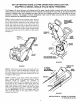
STEP 1: Remove machine from shipping carton. Remove
and discard cardboard from between all handles. The right
side of upper handle is positioned on the outside of lower
handle and should be moved to the inside of the lower
handle. Eye of eye-bolt must be on right side of machine at
lower handle. Raise upper handle until the lower ends seat
into concave area of lower handle. Tighten handle knowbs
securelly. Insert clean-out tool into holders on right handle.
See Figure 1.
DISCHARGE
CHUTE
INSTALL LOWER
CHUTE HANDLE
ONTO DISCHARGE
CHUTE
INSTALL
CLEAN-OUT
TOOL
UNFOLD
HANDLE
/
/
/
/
CARRIAGE
BOLTS
LOWER
CHUTE
HEX
TIGHTEN
KNOBS
SLIDE DISCHARGE CHUTE
FIGURE 2
FIGURE 1
STEP 2: Install lower chute handle onto chute with two
hex cap screws. Install chute/handle assembly onto
discharge opening and secure with three carriage bolts
and nuts. Tighten all nuts and bolts securely but, do not
overtighten. See Figure 2.
STEP 3: Measure auger clutch control cable extension
from a relaxed position to full extended position. Proper
extension should be between 1/2" minimum to
3/4"maximum extension. NOTE: Measure from the top of
spring (The top is in relation to where spring hooks into
auger clutch control). Loosen jam nut at the upper end of
cable. Hold threaded end of cable and then turn cable
clockwise until correct extension is achieved. Retighten
jam nut. IMPORTANT: DO NOT over tighten cable. The
cable must have slack for the auger brake to function
properly. See Figure 3.
1/2"MINIMUM
to 3/4" MAXIMUM
SPRING EXTENSION
AUGERCLUTCH
UPPER
HANDLE
FIGURE 3
INSTRUCTION No. 7100948 (I.R. 6/26/2006)
TP 300-5206-00-SX-SN