
Operation Manual


9
4. Ring
5. Rear grille
6. Connecting ring
7. Fixing plate
8. Fan body
9. Handle
10. Oscillation button
11. Stop switch
12. Low power switch
13. Medium power switch
14. High power switch
15. Turn-off timer
16. Telescopic tube
17. Height adjustment ring
18. Fixing screw
19. Base
20. Telescopic tube base
21. Shaft protector
ASSEMBLY
Assembling the base
• Remove the base (19) and the telescopic tube (16) from its cavity. Introduce
the base of the telescopic tube (20) into the base so that its flanges enter
the spaces in the base (19). To join the pieces, turn the tube (2) clockwise
as far as it will go.
• Extract the telescopic tube (16) to the desired height and adjust the height
of the fan using the height regulation ring (17).
• Fit the fan body (8) on the tube (16) and attach it by unscrewing the fixing
screw (18) slightly so that the telescopic tube (16) penetrates the body of
the fan ), then tighten the fixing screw again and check that both pieces
are attached.
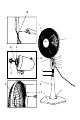
Assembling the grille and the blades
• Remove the motor shaft hood (2) and ring (4), and also remove the shaft
protector (21) between them. Fit the rear grille (5) over the shaft (8) so that
the projections on the motor shaft coincide with the orifices on the rear
grille (5)Fig 1.
• Fix the rear grille to the fan bodyusing the ring (4), tightening it in a clock-
work direction. Fig 2.
• Insert the blades (3) so that the slits on their upper parts meet the projec-
tions on the fan body (8). Fig 3
• Fix the blades turning the hood (2) anticlockwise. Check that they turn cor-
rectly.