
Operation Manual

10
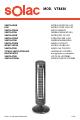
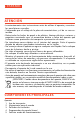
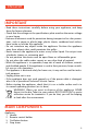
5. Operating mode selector
6. Speed selector
7. Start/stop button
8. Screen
9. Column A
10. Column B
11. Base A
12. Base B
13. Fixing screws
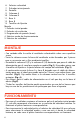
Remote control
1. Start/stop button
2. Oscillation button
3. Stop timer
4. Operating mode selector
5. Speed selector
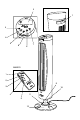
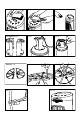
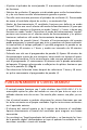
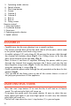
ASSEMBLY
• Carefully turn the fan over, placing it on a smooth surface.
• The column and the base of the fan each consist of two parts, which need
to be joined together and fixed using screws.
• Assemble column A (9) and column B (10) passing the power cable through
the channel left between them (Fig.1). Use 4 fixing screws to fix the two
parts to the bottom of the fan body (Fig. 2).
• Next, fit base A and base B together, allowing the power cable to pass
through the channel that remains between the 2 bases, and join the two
bases together using screws (Fig.3). Fix the two bases to the central column
using the remaining 4 screws (Fig. 4).
• Finally, guide the power cable through the rail provided on the base for this
purpose (Fig.5).
• *You can find all the fixing screws in one of the cavities there is in one of
the polyspan protections of the appliance.
USER INSTRUCTIONS
• Press the start /stop button (7) to start the fan; it will start on its lowest
speed. The relevant pilot light will come on.
• To increase the speed, press the speed selector (6) once to select the me-
dium speed and again if you want high speed. In each case, the relevant
pilot light will come on.
• The fan will stop when the start / stop button (7) is pressed again.