SMA / SBA SERIES power amplifiers specifications SIGNAL SIGNAL CH 4 www.sonodyne.
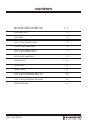
CONTENTS IMPORTANT SAFETY INFORMATION 1~2 INTRODUCTION 3 FEATURES 4 FIG. 1: FRONT PANEL LAYOUT 5 FRONT PANEL CONTROLS 6 FIG. 2: REAR PANEL LAYOUT 7 REAR PANEL CONTROLS 8 INSTALLATION 9 ~ 10 OPERATION 11 MAINTENANCE 12 FIG. 3: BLOCK DIAGRAM: SMA 250 13 FIG.
IMPORTANT SAFETY INFORMATION This operation manual contains important information regarding safety precautions, installation, performance, operation and maintenance of your SMA/ SBA Series power amplifiers. You should familiarize yourself with the contents of this manual before operating your amplifier. 1. Save the carton and packing material even if the equipment has arrived in good condition. Should 2. Read all documentation before operating your equipment. Retain all documentation for future 3. 4.
IMPORTANT SAFETY INFORMATION 13. Do not block fan intake or exhaust ports. Do not operate equipment on a surface or in an environment which may impede the normal flow of air around the unit, such as a bed, rug, weather sheet, carpet, or completely enclosed rack. If the unit is used in an extremely dusty or smoky 14. 15. 16. 17. 18. 19. 20. environment, the unit should be periodically “blown free” of foreign matter. Do not remove the cover.
INTRODUCTION Congratulations on choosing Sonodyne for your professional amplification requirements. The design of our SMA/SBA Series PA Power Amplifiers embraces all the aspects of a well designed amplifier. The visual design, mechanical, electrical and sonic parameters, along with our dedicated manufacturing process, have all been optimized to provide a professional tool that exhibits quality, reliability and longevity. The SMA/SBA Series amplifiers are 2 unit (3.5”) high, 19” wide, rack mountable units.
FEATURES ∑ Custom designed, 2RU heavy-duty steel chassis ∑ Symmetrical layout - even weight distribution ∑ ∑ ∑ ∑ ∑ ∑ ∑ ∑ ∑ ∑ Front rack mount ears Efficient power supply Efficient front to back cooling Thermally controlled axial fans. Balanced and unbalanced inputs and buffered attenuators. Input signal strapping (loop through) connectors Phantom power switch( selectable) Output through a Approved Terminal strip on the rear panel.
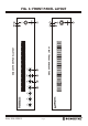
SMA/ SBA SERIES 7 CH 4 6 4 SBA 250P FRONT PANEL LAYOUT 5 MASTER SMA 250 FRONT PANEL LAYOUT Page 5 SIGNAL 3 SIGNAL 3 1 2 1 2 FIG.
FRONT PANEL CONTROLS Front panel: The functions of the controls and indicators on the SMA 250/ SBA 250P are as follows: 1. POWER SWITCH: Press the switch to up for power on and down for power off. At start-up (turn-on), 2. ON INDICATOR: This LED will illuminate RED and indicates that the amplifier is on and receiving mains power. 3. SIGNAL INDICATION: This green LED indicates the presence of the signal. 4.
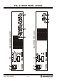
SMA/ SBA SERIES 13 13 Page 7 230V AC, 50/60Hz AC FUSE 3.15A,250V SB 12 230V AC, 50/60Hz AC FUSE 3.15A,250V SB 12 O.T. IN C 70 VAC O.T. IN C 70 VAC WHEN NOT IN USE. RETAIN LINK 70V / 100V OUTPUT. FOR GETTING CONNECT LINK LINK FOR 70V / 100V OHM DIRECT C 4 11 WHEN NOT IN USE. RETAIN LINK 70V / 100V OUTPUT.
REAR PANEL CONTROLS 8. BALANCED MICROPHONE INPUTS: All four inputs are dual mic/line. The microphone inputs is via a 3 pin Female XLR connector per channel. The mic input sensitivity is 1mV @ 200 Ohms. Reading from left to right across the rear panel, the inputs are 4, 3, 2, & 1. (Note: For SBA 250P there is a balanced Female XLR Line/Aux Input. The Line input sensitivity is 250mV. The SBA250P includes a 3 pin male XLR connector which can be use for (Line Out) Signal Linking to other similar amplifier.
INSTALLATION POWER REQUIREMENTS Power consumption for your model of the SMA 250/ SBA 250P amplifier is indicated on the rear panel for maximum output. Ensure that your mains voltage is the same as the rear panel mains voltage marker (± 10%). MOUNTING Your amplifier is designed for standard 19” rack mounting and occupies 2 EIA rack units (3.5”). The mounting centres are: Vertical: 3” (76.0 mm) Horizontal: 18.2” (461.8 mm) to 18.7” (470.
INSTALLATION HUM PROBLEMS Most equipment is designed for minimum hum when used under ideal conditions. When connected to other equipment, and to a safety earth in an electrically noisy environment, problems may occur.
OPERATION IMPORTANT: All signal source equipment should be adequately earthed. This not only ensures your safety but everybody else's as well. Faults can and do occur in mains connected equipment where the chassis can become “live” if it is not properly earthed. In these instances, the fault in a “floating” (ungrounded) piece of equipment will look for the shortest path to ground, which could possibly be your amplifier's input.
MAINTAINANCE Only competent or qualified persons should attempt any service or maintenance of your amplifier. Your new SMA/SBA Series amplifiers will need minimal maintenance. No internal adjustments need to be made to the unit to maintain optimum performance. To provide years of unhindered operation we suggest a maintenance inspection be carried out on a regular basis, say every 12 months or so.
SMA/ SBA SERIES Page 13 CH 4 CH 2 CH 1 MUTE CH 4 MUTE CH 2 MUTE MUTE CH -1 PRIORITY MUTING CH 1 -12dB BASS +12dB TREBLE -9dB +9dB THERMAL REC OUTPUT MUTE PUSH PULL OUTPUT STAGE MUTE COM COM 70V 100V MUTE O.T. IN (LINK) OUTPUT TERMINAL 4 OHMS DIRECT FIG.
SMA/ SBA SERIES FEMALE XLR MALE XLR INPUT INPUT LOOP LEVEL CONTROL Page 14 COM 70V 100V O.T. IN (LINK) COM 4 OHMS DIRECT OUTPUT TERMINAL FIG.
SPECIFICATIONS INPUT MAINS SUPPLY OUTPUT POWER @ 1% THD OUTPUTS INPUT SENSITIVITY TONE CONTROL REC OUT THD S/N RATIO ( @ 100V) NON A-WTD, POTS CENTRED FREQUENCY RESPONSE @4W @ 70V/100V NUMBER OF INPUTS SIZE (WxHxD) SHIPPING WEIGHT SPECIAL FEATURES SMA 250 (2RU) SBA 250P (2 RU) 250W a) 4E - Direct b) 70~100V - Through output Txfr.
SONODYNE A product of MUKHERJEE INNOVATION CENTRE SONODYNE ELECTRONICS CO PVT LTD H.O.: 98 NB Block E New Alipore, Kolkata 700053, INDIA T: +91 33 23990418, 23983406 F: +91 33 23967243 E: response@sonodyne.com www.sonodyne.