
User guide


Page 8
SMA/ SBA SERIES
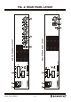
REAR PANEL CONTROLS
8. BALANCED MICROPHONE INPUTS: All four inputs are dual mic/line. The microphone inputs is via a 3 pin
Female XLR connector per channel. The mic input sensitivity is 1mV @ 200 Ohms. Reading from left to
right across the rear panel, the inputs are 4, 3, 2, & 1.
(Note: For SBA 250P there is a balanced Female XLR Line/Aux Input. The Line input sensitivity is 250mV.
The SBA250P includes a 3 pin male XLR connector which can be use for (Line Out) Signal Linking to other
similar amplifier. In some projects, the same input may be looped through to multiple amplifiers using this
method. Up to 6 amplifiers can be looped together without any noticeable loss in level. A distribution
amplifier should be used when more than 6 amplifiers need to be looped.)
The pin configuration for the female 3-pin XLR on each input is as follows:
Pin 1 = Signal Ground; Pin 2 = Hot (non-inverting or in phase); Pin 3 = Cold (inverting or reverse phase)
9. UNBALANCED STEREO LINE INPUT: For all the 4 channels the line/auxiliary inputs are via dual RCA
connectors per channel. the input sensitivity is 120 mV @ 100 kOhms. Reading from left to right across
the rear panel, the inputs are 4, 3, 2, & 1. (Note: This feature is not present for SBA 250P)
10. REC OUT: Dual RCA output connectors provided on the rear panel gives a line level output with a maximum
of 400 mV (± 80 mV) into 10 kOhms as a most standard requirement for tape recorders. This output is
sourced before the master gain control and as such, the REC output level is not influenced by the variation
of the master gain control. (Note : This feature is not present for SBA 250P )
11. SPEAKER OUTPUT TERMINAL STRIP: The screw terminals on the Rear panel provides Direct Speaker
Outputs and a Mute point. Reading from left to right the terminals are:
COM Common or “-” for low impedance speaker loads (4 ohms).
4 Positive “+” for 4 ohm speaker loads (use with common) This is the direct output from
internal amplification stage before the output transformer
O.T. IN Short this pin to 4 Ohms pin to connect the output transformer in circuit for 70/100V
operation only. For 4 Ohms operation this link must be kept open (not connected)
COM Common or “-” for 70V or 100V speaker loads (maximum load of 40 Ohms at 100V)
70 Positive “+” for 70V line speaker loads (use with common)
100 Positive “+” for 100v line speaker loads (use with common).
Please ensure that the correct “Common” is used. Low impedance and 70/100V loads can be used
simultaneously but please pay careful attention to the overall speaker load. When used individually, the
low impedance load should be 4 Ohms or higher while the 100V line load should not fall below 80 Ohms.
When both outputs are used simultaneously, ensure that total output power should not exceed 250W.
MUTE Remote Muting ON/OFF Connection (Not available for SBA 250P)
MUTE Remote Muting ON/OFF Connection (Not available for SBA 250P)
Channels 2 , 3 and 4 are muted when these two MUTE contacts are shorted together.
12. MAINS INPUT CONNECTOR: Your amplifier is provided with a 3 Pin IEC socket for mains connection. Use
the mains cable supplied with the unit to power up the unit. NOTE: Your unit must always be earthed!
13. MAINS FUSE: The Mains IEC socket has a Fuse compartment which carries the mains fuse of 3.15A Slow
Blow, always use the same rating and type of fuse while replacing.