
Modem User Manual


LZT 123 1834 29
5 System Connector Interface
5.1 Overview
Electrical connections to the wireless modem (except the antenna), are made through
the System Connector Interface. The system connector is a 60-pin, standard 0.05 in
(1.27 mm) pitch device.
The system connector allows both board-to-board and board-to-cable connections
to be made. Use a board-board connector to connect the wireless modem directly to
a PCB, and a board-cable connector to connect the radio device via a cable. Surface
mount mating connectors for the 60-pin system connector are available from Harwin
(part number M50-3113022).
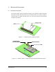
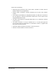
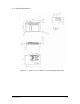
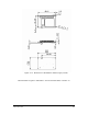
Figure 5.1-1 below shows the numbering of the connector pins.
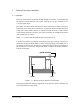
A ground connection is provided at the mounting hole next to the RF connector on
the wireless modem as shown below. Connect this ground point to the DGND pins of
the wireless modem by the shortest, low-impedance path possible. The purpose of
this connection is to allow any antenna ESD strikes to bypass the wireless modem’s
internal ground path.
pin 1
pin 2
pin 59
pin 60
ground connection
pin 1
pin 2
pin 59
pin 60
ground connection
Figure 5.1-1 Wireless modem, viewed from underneath
The following table gives the pin assignments for the system connector interface and
a short description for each signal.