
Modem User Manual

LZT 123 1834 61
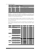
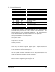
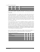
5.11.6 SIM Card Interface
Pin Name Direction Function
15 SIMVCC Output 1.8V or 3.0V SIM card supply
16 SIMDET Input SIM presence detection
17 SIMRST Output SIM card reset signal
18 SIMDAT In/Out SIM card data
19 SIMCLK Output SIM card clock signal
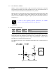
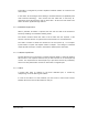
This interface allows the user to communicate with the smart (SIM) card in the user
application. The GR64 offers alternative arrangements for accessing the SIM
depending on which variant of the GR64 is used. Both variants provide this interface
through the system connector, referred to as the
external
or
remote
SIM interface to
distinguish it from the integrated SIM interface.
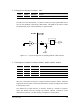
The maximum distance between the SIM card holder and the wireless modem is
70cm. SIM holders placed further than this distance may not meet the SIM interface
performance specification.
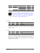
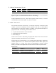
This SIM interface allows the use of 3 V and 1.8 V SIM cards (5V is unsupported). The
wireless modem automatically detects the SIM type, switching the signal voltages
accordingly.
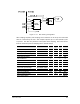
Signal Parameter Mode
Min Typ Max Unit
1.8V 1.71 1.8 1.89 V
SIM supply voltage
3.0V 2.75 2.9 3.05 V
Short circuit current 10 50 mA
Quiescent Supply Current 3.0V 20
µA
Output Capacitance 0.3 2
µF
SIMVCC
Output Capacitor ESR 0.01 1.0
1.8V 0.7xSIMVCC V
High level input voltage (V
IH
)
3.0V 0.7xSIMVCC V
1.8V 0.2xSIMVCC V
Low level input voltage (V
IL
)
3.0V 0.4 V
1.8V 0.8xSIMVCC V
High level output voltage (V
OH
)
3.0V 0.8xSIMVCC V
1.8V 0.4 V
SIMDAT
Low level output voltage (V
OL
)
3.0V 0.4 V
1.8V 0.9xSIMVCC V
High level output voltage (V
OH
)
3.0V 0.9xSIMVCC V
1.8V 0.4 V
SIMCLK
SIMRST
Low level output voltage (V
OL
)
3.0V 0.4 V