
Modem User Manual

LZT 123 1834 66
Some GPIO is configured to provide a keyboard interface (details are covered in the
next section).
In the GR64, all IO undergoes level shifting to maintain backward compatibility with
older interface technology. Users should not that GPIO that is used truly bi-
directional cannot be open drain type on both sides. At least one side needs to be
able to drive the signal both high and low.
5.15.1 Embedded Applications
When a particular IO feature is required, the user sets the state of the relevant IO
blocks by disabling one set before enabling others.
The wireless modem checks the state of the IO when the user requests a new
function. The new function is rejected if the current function is not released first.
The states of GPIO
n
to GPIO
m
are retained for the next power up. For example,
inputs remain as inputs and outputs remain as outputs. The voltage of a defined
output pin will still drop to 0 Volts in the wireless modem power down state.
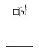
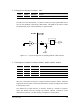
5.15.2 LED/IO6 Capabilities
The LED function pin can be used as a general purpose digital I/O when the flashing
LED function is not required. However, this pin does not have an on-board pull-up
resistor. It is required that an external pull-up or pull-down resistor be provided by
the host circuitry when either not used or when used as a digital input.
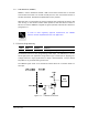
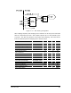
5.15.3 ADC4
A further ADC input (in addition to the three dedicated pins) is created by
multiplexing one of the GPIO signals (GPIO5).
In order to use ADC4 as a GPIO interface you must insert a 1kohm series resistor
between the host circuit and the module on this pin.