
Modem User Manual

LZT 123 1834 69
5.18 I
2
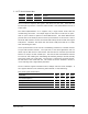
C Serial Control Bus
Pin Name Direction Function
29 SDA In/Out I
2
C data
30 SCL Output I
2
C clock
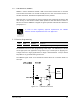
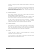
The I
2
C interface comprises two signals; data (SDA) and clock (SCL). Both SDA and
SCL have pull-up resistors. Therefore, when the bus is free, both SDA and SCL are in
a HIGH state.
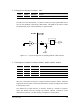
The GR64 implementation of I
2
C supports only a single master mode, with the
module being the master. The output stages of SDA and SCL must have an open-
drain or open-collector to perform a wired-AND function. The wired-AND function
provides the I
2
C bus ability to perform clock synchronization on the SCL line. Due to
the wired-AND function, the SCL line will be held LOW by the device with the longest
LOW period. Therefore, the device with the shorter LOW period will be in a HIGH
wait-state during this time.
Clock synchronization can be used as a handshaking mechanism, to enable receivers
to cope with fast data transfers. On a byte level, a slave (host application-side) I
2
C
device may be able receive a data transfer, but need time to store the byte received
before it is ready to receive another byte. The slave/receiver will therefore hold the
SCL line low, after sending the acknowledge bit following the byte received, thereby
forcing the master into a wait state. Once the SCL is released by the slave/receiver,
the wait state of the master will end. This feature of the I2C standard is known as
clock-stretching
and is supported by the GR64.
The I2C interface supports Standard-mode (100kbps) and Fast-mode (400kbps). It
also supports Normal (7-bit) addressing and Extended (10-bit) addressing.
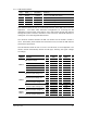
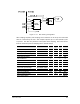
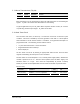
Fast-mode signal characteristics
Parameter
Min Typ Max Unit
SCL clock frequency 0
400 kHz
LOW period of the SCL clock 1.3
µs
HIGH period of the SCL clock 0.6
µs
Data hold time 0
0.9
µs
Capacitive load for each bus line
400 pF