
COLOR VIDEO MONITOR OPERATION MANUAL


48
Chapter 2 Menu
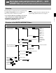
INPUT CONFIGURATION C1
REMOTE C2
PASSWORD C3
SYSTEM CONFIGURATION C4
ON SCREEN SET C5
ALIGNMENT C6
WHITE UNIFORMITY C7
EXTEND MENU C8
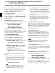
ALIGNMENT (1/3) — ROTATION
ALIGNMENT (2/3) — H PIN
ALIGNMENT (3/3) — V STATIC CONV
CONV FINE ADJUST... C61 — ADJUST C611
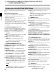
The ALIGNMENT menu is used for adjusting
geometry and convergence.
Note
Adjust the beam landing ([C8]) after the geometry and
convergence adjustments have been completed.
The following adjustments can be performed with the
three pages of the ALIGNMENT menu.
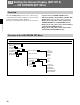
Structure of the ALIGNMENT Menu
Overview
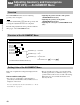
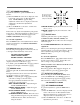
Setting Lists of the ALIGNMENT Menu
This section explains the setting lists displayed in the
menu.
How to read the setting lists
• For purposes of explanation, each setting list is
preceded by a menu number. These numbers are not
displayed on the screen.
For more information about the menu number, see “About
menu numbers” on page 23.
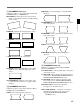
[C6] Adjusting Geometry and Convergence
(SET UP 6) — ALIGNMENT Menu
• Adjusting the position and size of the picture
(ALIGNMENT menu (1/3))
• Adjusting the geometry of the picture
(ALIGNMENT menu (2/3))
• Adjusting the convergence (ALIGNMENT menu
(3/3))
Level 1 Level 2 Level 3 Level 4
• The arrow mark (÷) refers you to another setting
list that appears after you make the setting, or to an
operation that is carried out as a result of the setting.
When there is no arrow mark, the menu does not
have any sub-list.
1) BVM-D32E1WU/D32E1WE/D32E1WA only
1) 1)