3-198-136-11(1) Component Video Switcher Installation Manual Owner’s Record The model and serial numbers are located on the rear panel. Record the model and serial numbers in the spaces provided below. Refer to them whenever you call upon your Sony dealer regarding this product. Model No. CAV-CVS12ES 2007 Sony Corporation Serial No.
WARNING To reduce the risk of fire or electric shock, do not expose this apparatus to rain or moisture. To reduce the risk of fire or electric shock, do not place objects filled with liquids, such as vases, on the apparatus. CAUTION You are cautioned that any changes or modifications not expressly approved in this manual could void your authority to operate this equipment.
Table of Contents Chapter 1 Getting Started Features 4 Unpacking 5 Parts and Controls 6 Chapter 2 Setting up the Component Video Switcher Installing the Component Video Switcher 8 Hooking up the Component Video Switcher 10 Chapter 3 Other Information Precautions 12 Troubleshooting Specifications 13 14 US
Chapter 1 Getting Started This chapter provides information on the features, parts, and controls of the Component Video Switcher. US Features You can control up to twelve video sources in up to twelve zones (e.g., rooms or areas) with this CAV-CVS12ES Component Video Switcher. The Component Video Switcher allows you to: – Distribute HD video signals in up to twelve zones. – Up-convert up to four composite video signals to component video signals for higher quality.
Unpacking Getting Started The CAV-CVS12ES Component Video Switcher includes the following: CAV-CVS12ES Component Video Switcher AC power cord Installation Manual (this manual) Rack-mount brackets (2) US
Parts and Controls Getting Started Front panel of the Component Video Switcher ZONE 1 2 3 4 5 6 7 8 9 10 11 12 POWER SOURCE 1 2 3 4 5 6 POWER switch Press to turn the power on or off. ZONE indicator The selected zone number lights up. 7 8 9 2 3 … 10 11 12 SOURCE indicator The source number selected for the zone lights up. When the zone does not select any source component, no SOURCE indicator lights up.
SOURCE 1 IN OUT SOURCE 2 IN OUT SOURCE 3 IN SOURCE 4 OUT IN OUT SOURCE 5 IN OUT Getting Started Rear panel of the Component Video Switcher SOURCE 6 IN OUT SOURCE 7 IN OUT SOURCE 8 IN SOURCE 9 SOURCE 10 SOURCE 11 SOURCE 12 OUT Y IN OUT IN ASSIGNABLE PB S9 PR OUT ASSIGNABLE VIDEO OUT VIDEO OUT VIDEO OUT VIDEO OUT VIDEO OUT VIDEO OUT VIDEO OUT VIDEO OUT VIDEO OUT VIDEO OUT VIDEO OUT VIDEO OUT ZONE 2 ZONE 3 ZONE 4 ZONE 5 ZONE 6 ZONE 7 ZONE 8 ZONE 9 ZONE 10 ZO
Chapter 2 Setting up the Component Video Switcher This chapter provides information on the Component Video Switcher regarding installation, hookups and settings. US Installing the Component Video Switcher When installing the Component Video Switcher, note the following: Place the Component Video Switcher on a flat and level surface.
Using rack-mount brackets You can also mount the Component Video Switcher into a rack. Make sure that you measure the space needed before mounting. 1 Detach the four feet of the Component Video Switcher. 2 Detach the six screws attached to the Component Video Switcher as shown below.
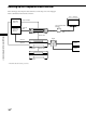
Hooking up the Component Video Switcher Before hooking up the Component Video Switcher, be sure the AC power cord is unplugged. Refer to the illustration below for the connection. Zone 1 ~ 12 Display Audio/Video Source 1 ~ 8 Audio/Video Source 9 ~ 12 (VHS, etc.
CAT5 RJ45 Video Pinout The CAT5 RJ45 pinouts use the T568B standard. Refer to the illustration below. Pinout Wire color BLUE/Pb (R) White/Orange Pin 2 BLUE/Pb (T) Orange Pin 3 GREEN/Y (R) White/Green Pin 4 GND Blue Pin 5 +11V White/Blue Pin 6 GREEN/Y (T) Green Pin 7 RED/Pr (R) White/Brown Pin 8 RED/Pr (T) Brown Setting up the Component Video Switcher Pin 1 CAT5 cable Before installation, be sure to verify the CAT5 wiring connection is correct.
Chapter 3 Other Information This chapter provides additional information that will help you understand and maintain your system. Precautions On safety Should any solid object or liquid fall into the cabinet, unplug the Component Video Switcher and have it checked by a qualified service technician before operating it any further. On power sources Before operating the unit, check that the operating voltage of the unit is identical to that of your local power supply.
Troubleshooting If you experience any of the following difficulties while using the Component Video Switcher, use this troubleshooting guide to help you to remedy the problem. Should any problem persist, consult your nearest Sony dealer. There is no picture, or an unclear picture appears on the TV screen or monitor. Select the appropriate input on the Main Unit. Set your TV to the appropriate input mode. Move your TV away from the audio components. The picture does not appear properly.
Specifications Video input Y: 1.0Vp-p/75 ohm Pb: 0.7Vp-p/75 ohm Pr: 0.7Vp-p/75 ohm Video output CAT5 RJ45 output General Other Information IR input: accept 40 kHz IR modulation frequency Power requirements: 120 V AC, 60 Hz Power consumption: 33 W Operating temperature: 0°C to 40°C (32°F to 104°F) Dimensions: 435 100 290 mm (17 1/4 4 11 1/2 inches) (w/h/d) (including projecting parts) Mass: 4.
Sony Corporation Printed in Malaysia