3-203-834-12(1) DFS-700/700P DME Switcher Operating Instructions Before operating the unit, please read this manual thoroughly and retain it for future reference.
Owner’s Record The model and serial numbers are located in the rear. Record these numbers in the spaces provided below. Refer to them whenever you call upon your Sony dealer regarding this product. Model No. Serial No. WARNING To prevent fire or shock hazard, do not expose the unit to rain or moisture. For customers in the USA (DFS-700 only) This equipment has been tested and found to comply with the limits for a Class A digital device, pursuant to Part 15 of the FCC Rules.
Table of Contents Chapter 1 Overview Features of This System ................................................1-1 Option Boards ................................................................1-3 Chapter 2 Location and Function of Parts and Controls Control Panel ................................................................. 2-1 Processor Unit ..............................................................2-13 Front Panel .....................................................................
Table of Contents Chapter 3 Basic Operation (Continued) Inserting Characters and Graphics (1) — Title Key ...3-33 Luminance Key .............................................................. 3-33 Chroma Keying .............................................................. 3-36 Masking Part of a Title Key............................................ 3-44 Inserting Characters and Graphics (2) — Downstream Key ................................................ 3-45 Setting Up a Transition .....................
Chapter 5 Control From Editing Control Units Control From the PVE-500 ............................................ 5-1 Preparations ...................................................................... 5-2 Cut Editing ....................................................................... 5-2 A/B Roll Editing ............................................................... 5-3 Control From the BVE-600............................................ 5-5 Preparations ............................................
Table of Contents Appendixes Warning Messages ........................................................ A-1 Effect Type List .............................................................. A-3 Effect Control Parameter List ....................................... A-5 Effect Motion Types ..................................................... A-21 Effect Pattern Variant Forms and Decorations ......... A-22 Effect Pattern Image List ............................................ A-29 To Exchange the Button Labels .
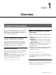
Chapter 1 Overview Features of This System The Sony DFS-700/700P DME Switcher is a Digital Multi Effects system, offering high-performance effects at high image quality. The system consists of a processor unit and control panel. Support for fully digital component systems with SDI inputs and outputs This system provides SDI interfaces as standard equipment. This allows it to be incorporated in fully digital linear editing systems using DVCAM-series, Betacam SX-series, and other digital VCRs.
Features of This System Chapter 1 Overview Color correction function Interfacing with editors A YUV color correction function is provided for white balance adjustment and general color adjustment. This system is equipped with I/O interfaces for two sets of control signals, allowing operation together with various editing control units.
Option Boards The DFS-700/700P system has the following option boards. When this board is installed, it allows all eight video inputs to be used as either SDI or analog component inputs. When using this board, you can select the types of the optional inputs individually, using the setup menu. This board provides a second DME channel, enabling two-picture box, two-picture brick, and other effects.
Chapter 2 Location and Function of Parts and Controls Control Panel This section describes the control panel, which is divided into several sections, as shown below. See the page numbers shown in parenthesis for more details. Note If you make an error in operation, a warning sound may occur. You can switch off this audible warning (see page 6-10).
Control Panel 1 Delegation section 3 Frame memory buttons 1 Delegation buttons CCR AUXILIARY 2 AUXILIARY buttons BLACK 1 TITLE 1 TITLE 2 SOURCE SOURCE 2 Chapter 2 Location and Function of Parts and Controls 1 Delegation buttons Use these buttons to delegate the input signal corresponding to the selected AUXILIARY button to the corresponding function. Pressing one of these buttons lights it, and the corresponding AUXILIARY button also lights. Any other previously lit delegation button goes off.
2 Primary cross-point bus section BACKGROUND 1 BACKGROUND bus buttons BLACK 1 2 3 4 5 6 7 8 MEMORY INT VIDEO 2 3 4 5 6 7 8 MEMORY INT VIDEO FOREGROUND 2 FOREGROUND bus buttons BLACK 1 2 FOREGROUND bus buttons Select the image to form the foreground for an effect (or the “new” video in a transition). The functions of the buttons are the same as in the BACKGROUND bus buttons.
Control Panel 3 Effect transition section 2 Display window mode indicators 3 SET button 1 TRANS RATE display window EFFECT DSK TRANS RATE FTB 9 N/R button SET 4 MIX button q; REV button MIX EFFECT N/R REV 5 EFFECT button Chapter 2 Location and Function of Parts and Controls TITLE 6 TITLE button CUT 7 CUT button 8 AUTO TRANS button AUTO TRANS 1 TRANS (transition) RATE display window This shows the transition time for effects, downstream keys, and fade-to-black, in units of frames.
9 N/R (normal/reverse) button To carry out an effect in normal/reverse (i.e. alternating) mode, press this button, turning it on. It lights automatically for animation effects and title keys. qa Fader lever Move this to carry out an effect transition manually. Note After powering the system on, move the fader lever to the end of its travel once in each direction. This ensures that the fader lever will function correctly.
Control Panel 5 PATTERN/KEY PAD buttons These function as shown in the following table, according to the selected mode. Changing labels You can change the labels on the buttons, using the supplied labels. For details of how to change the labels, see page A-63. Functions of the PATTERN/KEY PAD buttons Mode Button Chapter 2 Location and Function of Parts and Controls DIRECT PATTERN PATTERN TRANS USER PGM SNAP SHOT DIRECT RECALL 0 to 9 Select the pattern shown on the button.
3 DSK (downstream keyer) button Press this button, turning it on, to insert the downstream key set by the DSK section buttons in the menu control section into the program output video. By pressing the SET button in the effect transition section, you can set the downstream key transition time.
Control Panel MASK button: Press this button to mask off a part of the key source signal. When you press this button, it lights, and the system is now in mask mode, and you can select a rectangular mask in the effect control section. Normally, the area outside the mask rectangle is the area which is masked. To invert the mask, so that the area inside the rectangle is masked, set INVERT (F5) to ON in the effect control section. Press the button once more to turn it off and end mask mode.
5 SHIFT button When a button in the menu control section is lit, but the corresponding menu is not displayed in the effect control section, hold down the SHIFT button and press the lit button. This brings up the menu, without interrupting the function selection, and leaving the button lit.
Control Panel 8 Effect control section 1 Menu display Chapter 2 Location and Function of Parts and Controls 2 INITIAL button INITIAL 3 PAGE button 4 PATTERN ADJ button PATTERN ADJ PAGE F1 F2 F3 F4 F5 6 F1 to F5 buttons 5 Control knobs 1 Menu display This shows system and effect settings. Watch this display while checking and adjusting the settings.
• Changing a setting value preceded by “+” (setup menu operations) Hold down the corresponding F button (F1 to F5), and turn the control knob. • Changing a setting value followed by “+” (user program effect setting operations) Hold down the corresponding F button (F1 to F5), and enter the numeric value using the numeric keypad.
Control Panel 4 HOLD INPUT button To hold the primary cross-point bus settings and the auxiliary bus settings (signal selections) fixed when recalling a snapshot, press this button. When you press this button, it lights, and when you recall a snapshot, the system is in the hold input mode. When you recall a snapshot in this mode, all settings are recreated on the control panel except those relating to the primary cross-point bus and the auxiliary bus.
Processor Unit Front Panel Power indicator Power switch Chapter 2 Location and Function of Parts and Controls Power switch and indicator This powers the unit on and off. Press the “ ” side of the switch to power on, and the “ ” side to power off. When the power is on, the power indicator lights amber.
Processor Unit Chapter 2 Location and Function of Parts and Controls 1 PGM OUT (program output) connectors These output the final program output, that is, the video to which effects have been applied. Connect to VTR (recorder) and program monitor video input connectors. The following four types of output are provided, each with two channels (1 and 2). SDI (BNC): Output serial digital signals (270 MHz). COMPOSITE (BNC): Output composite video signals.
8 PVW (preview) connector (BNC-type) This is an analog composite preview output. The signal output is the same as the program output after completion of the effect transition. It is not possible to include the title area. 9 BLACK BURST OUT 1 to 3 connectors (BNCtype) These output the black burst signals generated by the synchronizing signal generator internal to this unit. When an external synchronizing signal is input to the REF.
Chapter 3 Basic Operation DME Switcher Introduction This section selects two of the many effects provided by the DFS-700/ 700P as examples, and describes the basic flow of operations to use them. It also describes the demonstration function, which automatically executes one hundred sample effects. Sequence of Operations The flow charts below show the general sequence of operations when using a DME switcher.
DME Switcher Introduction Example Operation (1): Wipe In this example we’ll use the AUTO TRANS button, to make a wipe, with the new image appearing from the center of the screen. Setting items As an example, we’ll set the control panel as follows.
Procedure 6 USER PGM 1 TITLE 2 DSK EDGE LUM TRAIL SHADOW SNAP SHOT STATUS EDIT EDITOR LUM LUM GPI CRK CRK SET UP MASK MASK SHIFT CCR BORDER BEVELD EDGE MASK INITIAL EDIT RECALL LIGHTING MATTES BORDER PATTERN ADJ PAGE F1 F2 F3 F4 FTB CCR TITLE 1 TITLE 2 SOURCE SOURCE DSK FILL SUPER BG FRGD 2 MEMORY F5 EFFECT DSK TRANS RATE FRAME FREEZ 2 3 4 5 6 7 8 MEMORY INT VIDEO TITLE 2 3 4 5 6 7 8 MEMORY INT VIDEO CUT AUXILIARY LEARN SOFT MIX LOCATION HOLD
DME Switcher Introduction 5 Press button 9 in the pattern/numeric keypad. The button lights, and this selects the wipe assigned to this button (pattern number 24). The PATTERN NUMBER display window shows “0024”. 6 Press the SET button once or twice, so that the EFFECT display window mode indicator lights. (If it is already lit, omit this step.) 7 In the pattern/numeric keypad, press buttons 3 and 0 in that order. The TRANS RATE display window shows “.3.0.”.
Example Operation (2): Picture-in-Picture Using the fader lever, we’ll insert the foreground image within the background image. We’ll apply a border around the edge of the foreground image. Setting items As an example, we’ll set the control panel as follows.
DME Switcher Introduction Procedure 8 5 USER PGM 1 TITLE 2 DSK SNAP SHOT EDGE STATUS EDIT 2 EDITOR LUM LUM GPI CRK CRK SET UP MASK MASK SHIFT CCR LUM TRAIL SHADOW BORDER BEVELD EDGE MASK INITIAL EDIT RECALL LIGHTING MATTES BORDER PATTERN ADJ PAGE F1 F2 F3 F4 EFFECT DSK FTB TRANS RATE CCR AUXILIARY LEARN SOFT TITLE 1 TITLE 2 SOURCE SOURCE DSK FILL SUPER BG FRGD 2 MEMORY FRAME FREEZ MEMORY INT VIDEO MIX F5 LOCATION HOLD INPUT PATTERN NUMBER SET SET EFFECT N
6 In the numeric keypad, press buttons 1, 1, 0, 0, in that order. The PATTERN NUMBER display window shows “1.1.0.0.”. Dots appear to the lower right of the digits. 7 Press the ENTER button. The dots to the lower right of the digits disappear, and picture-inpicture, or pattern number 1100, is selected. 8 In the menu control section, press the BORDER button. The button lights, enabling the border. 9 Move the fader lever to the opposite end.
DME Switcher Introduction Demonstration The DFS-700/700P is equipped with a demonstration function, which automatically plays back one hundred effects stored in ROM in the processor unit. The effects (which by factory default are snapshots 0 to 99) have been chosen to demonstrate the features of the DFS-700/700P as effectively as possible. For maximum effect, the demonstration function uses the signals connected to VIDEO INPUT connectors 1 and 2, and the internal video signal.
To end the demonstration Press the AUTO TRANS button once more. The demonstration ends, and the control panel settings are those of the last effect in the demonstration.
DME Switcher Introduction Using the Menus This unit incorporates menus for various effect settings and internal color matte settings, and also a setup menu for system settings. This section describes the basic menu operation.
Changing settings • For settings with values shown in letters, press the corresponding one of buttons F1 to F5. In the text, this is shown as “the F1(SELECT) button,” with the setting name after the button name F1 to F5. • To change a setting with a numerical value, turn the corresponding one of control knobs F1 to F5. In the text, this is shown as “the F2(Lum) knob,” with the setting name after the knob name F1 to F5.
Selecting Images Background Image and Foreground Image Background and foreground in a transition effect In a transition from one image to another, the old image is referred to as the “background image”. The new image, which replaces the old image, is referred to as the “foreground image”. When a transition completes, the background image and foreground image are interchanged.
Selecting the background image and foreground image As the background image and foreground image you can select any of the video signals connected to the VIDEO INPUT 1 to 8 connectors of the processor unit (corresponding to BACKGROUND/FOREGROUND bus buttons 1 to 8), a freeze frame stored in the frame memory (MEMORY button), or internal pattern signal (INT VIDEO button).
Selecting Images Switching the internal video signal selected by the INT VIDEO button To switch the internal video signal selected by pressing the INT VIDEO button on either the background bus or foreground bus, use the following procedure.
Previewing the image after an effect is executed Select the background image and foreground image, and set up the effect, then move the fader lever to the opposite end. You can now check on the program monitor the result of carrying out the currently set effect. If a preview monitor is connected, you can check the foreground image on the preview monitor.
Selecting Images Selecting Signals Output to the Auxiliary Bus Delegation buttons USER PGM 1 TITLE 2 DSK SNAP SHOT EDGE STATUS EDIT EDITOR LUM LUM GPI CRK CRK SET UP MASK MASK SHIFT CCR LUM TRAIL SHADOW BORDER BEVELD EDGE MASK INITIAL EDIT RECALL LIGHTING MATTES BORDER PATTERN ADJ PAGE F1 F2 F3 F4 EFFECT DSK FTB TRANS RATE CCR AUXILIARY LEARN SOFT TITLE 1 TITLE 2 SOURCE SOURCE DSK FILL SUPER BG FRGD 2 MEMORY FRAME FREEZ MEMORY INT VIDEO MIX EFFECT F5 LOCATION
Selecting an Effect This section describes the types of effects you can use on this system, and how to select an effect. Types of Effect The DFS-700/700P has more than 450 built-in effect patterns provided as standard. Each pattern is identified by a number, and the patterns are grouped together under headings such as “wipe” and “picture-in-picture”. For the differences between transition and animation effects, see the section “Background Image and Foreground Image” (page 3-12).
Selecting an Effect Example Effects This section shows as examples the effect patterns (“direct patterns”) which you can access simply by pressing a button in the pattern/numeric keypad. Note that the effect patterns shown below are the factory default assignments, and you can change the patterns assigned to buttons 0 to 9 and P IN P/RST. For details of how to change the assignments, see the section “Changing Direct Pattern Assignments” (page 4-1).
4 Pattern number: 700 Effect type: matrix wipe Motion type: transition The foreground image appears in the upper left corner, and fills the screen in a series of vertical strips. 5 Pattern number: 1300 Effect type: slide Motion type: transition Chapter 3 Basic Operation The foreground image appears from the right, and slides over the background image to the left.
Selecting an Effect 2 Pattern number: 2100 Effect type: page turn Motion type: transition The foreground image appears as though progressively covering the background image. 3 Pattern number: 2200 Effect type: sphere Motion type: transition Chapter 3 Basic Operation The foreground image appears in a ball shape in the upper right. It “bounces” on the bottom of the screen, then when it reaches the top, turns into a plane and fills the screen, covering the background image.
Nonlinear effects These effects include effects such as ripples, under names such as lens, burst, explosion, swirl, and rings. Ripple Lens Swirl Explosion These effects combine two foreground images with the background image. They include two-channel picture-in-picture, two-picture intersect, twopicture brick, two-channel page turn, and so on. Two-channel picture-in-picture Two-picture Intersect Masked flip Note To use two-channel DME effects requires the optional BKDF-711 2nd Channel DME Board.
Selecting an Effect 3D mapping effects These effects use nonlinear image processing techniques. They include 3D page turn, 3D beveled edge, and so on. 3D wave Chapter 3 Basic Operation Three-picture cube 3D page turn Multi-cube 3D beveled edge 3D cylinder Note Using 3D mapping effects requires the optional BKDF-712 3D Video Mapping Effects Board. Using the three-picture cube effect also requires the optional BKDF-711 2nd Channel DME Board.
Selection in Direct Pattern Selection Mode In the direct pattern selection mode, pressing any button (other than INS, DEL, UP, DOWN, or ENTER) in the pattern/numeric keypad directly selects an effect pattern. For details of the effects assigned by factory default to the buttons in the pattern/ numeric keypad, see the previous section “Example Effects” (page 3-18). Procedure To select an effect pattern in the direct pattern selection mode, use the following procedure.
Selecting an Effect Selection in Pattern Number Specification Mode In the pattern number specification mode, you select the desired effect pattern by entering the number. Procedure To select an effect pattern in the pattern number specification mode, use the following procedure. Note If the EDIT button in the user program section (see page 2-11) is lit, first press it, turning it off.
If you enter a wrong number Before pressing the ENTER button press the P IN P/RST button to cancel the wrong number, then enter the correct number. Note If you enter an invalid number (a number with no corresponding pattern), this is automatically corrected to the closest valid number larger than the number you entered. However, if you enter a number larger than 9309 this is corrected to pattern number 0001. Adjusting the number before confirming To increment the number by one, press the UP button.
Modifying the Boundary — Border, Soft Edge, Beveled Edge, and Crop You can apply a border to the boundary between the foreground image and background image, or mask unwanted parts of the image. There are four effects for modifying the boundary, as follows. You can use all four simultaneously. Border: apply a border to the image boundary. Soft edge: blur the image boundary. Beveled edge: apply a bevel to the image boundary. Crop: adjust the image boundary position, to eliminate unwanted parts.
To blur the image boundary Use the following procedure. 1 Press the SOFT button in the EDGE section, turning it on, and display page 1 of the EDGE menu. EDGE Border Soft BvlWid BVLTYP BvlInt 1/2 0-100 0-100 –100-100 01-20 0-100 PAGE 2 F1 F2 F3 F4 F5 Turn the F2(Soft) knob, to set the degree of boundary blurring. To apply a beveled edge to the image boundary Use the following procedure.
Modifying the Boundary — Border, Soft Edge, Beveled Edge, and Crop Indications in the EDGE menu with square brackets [ ] The parameters in the EDGE menu for functions which are turned off appear in square brackets [ ]. For example, when the border function is off, when you display the EDGE menu the setting for Border appears in square brackets. In this state the knob adjustment is still valid. When you press the BORDER button, turning the function on, the new setting is reflected accordingly.
Changing the Pattern Position and Size — Location (X)(Y)(Z) You can adjust the position and size of an effect pattern when inserting a foreground image into the background image. Note For some effect patterns it is not possible to change their position and size. If pressing the LOCATION button does not turn it on, it means that one of those effect patterns is selected.
Changing the Pattern Position and Size — Location (X)(Y)(Z) 3 To move the pattern in the depth direction (z-axis), turn the Z-knob in the location section.
Modifying the Pattern — User Modifiable Effects User modifiable effects are those effects for which you can modify the effect pattern by varying the parameters. The variable parameters vary from effect to effect. For the pattern number of user modifiable effects, and the variable parameters, see the section “Effect Control Parameter List” (page A-5) Procedure To modify the effect pattern by varying the parameters, use the following procedure.
Modifying the Pattern — User Modifiable Effects Example of user modifiable effect parameters As an example, if you select mosaic (pattern number 1016), the following parameters appear in the menu display. 1016 Size Aspect Soft MskAsp TYPE 1/1 0-100 0-100 0-100 0-100 FLAT PAGE F1 F2 F3 F4 F5 For the effect of the parameters, see the following figure.
Inserting Characters and Graphics (1) — Title Key You can insert (or superimpose) text and graphics into the background image while applying effects. You can use either a luminance key or a chroma key for this insertion. Luminance Key In a luminance key, a certain luminance level in the foreground image is used as the threshold for creating the key signal, and the corresponding part of the foreground image is inserted into the background image.
Inserting Characters and Graphics (1) — Title Key Procedure To insert text and graphics in a background image by means of a luminance key, use the following procedure.
4 In the TITLE section of the menu control section, press a LUM button, turning it on. The luminance key menu appears in the menu display. In the following example, the LUM button in column 1 is lit. T1LUM Clip Gain INVERT FILL Densty 1/1 0-100 0-100 OFF VIDEO 0-100 PAGE 5 F1 F2 F3 F4 F5 Either press the CUT button in the effect transition section, or move the fader lever. A composite of the foreground and background images appears in the program monitor.
Inserting Characters and Graphics (1) — Title Key Chroma Keying In chroma keying, a key signal is created based on a specific reference color in the foreground image, and used to replace the corresponding parts of the foreground image by the background image. Normally, the foreground image is created with a plain blue background, which is then replaced by the background image.
Auto chroma keying To combine the background image and foreground image by auto chroma keying, use the following procedure.
Inserting Characters and Graphics (1) — Title Key 4 In the TITLE section of the menu control section, press the CRK button, turning it on. In the menu display page 1 of the chroma key menu appears. The following example appears when the CRK button in column 1 is lit. T1CRK Clip Gain Hue Angle 1/3 0-100 0-100 0-99 0-100 PAGE 5 F1 F2 F3 F4 AUTO F5 Press the F5(AUTO) button. In the program monitor screen, the foreground image appears with a white box cursor.
Making fine adjustments to the composite image Following the manual chroma key procedure (see next page), adjust the hue, clip, and gain for the specified chroma key color. You can also adjust the luminance of the part cut out by the chroma key. To switch between the composite image and the background image Press the CUT button. This toggles between the composite image and the background image.
Inserting Characters and Graphics (1) — Title Key Manual chroma key To combine the background image and foreground image by manual chroma keying, use the following procedure.
4 Watching the composite image on the program monitor, in page 1 of the chroma key menu, adjust the hue, clip, and gain. When the background part of the foreground image is not completely replaced by the background image Adjust the hue with the F3(Hue) knob and the clip with the F1(Clip) knob. When the outline of the foreground image is not clear Adjust the clip with the F1(Clip) knob and the gain with the F2(Gain) knob.
Inserting Characters and Graphics (1) — Title Key Adjusting the hue range for chroma keying (the “angle” setting) If there are fluctuations in the background color in the foreground image, it may not be immediately possible to key the background image into the whole of the desired background. In this case, you can correct this by increasing the range of hues (the “angle” setting) used for chroma keying. (This means using a wider-angled sector of the hue circle.
4 Watching the composite image on the program monitor, turn the F3(Hue) and F2(Sat) knobs, until the boundary between the background image and foreground image provides a natural match of hue and saturation. Creating a composite image with a semi-transparent foreground image (density function) You can make the inserted image semi-transparent, and insert it into the background image. Use the following procedure.
Inserting Characters and Graphics (1) — Title Key Masking Part of a Title Key You can apply a rectangular mask, to eliminate unwanted parts of the key. The masked part is filled with the background image. This operation is common to luminance and chroma keys.
Inserting Characters and Graphics (2) — Downstream Key As its name implies, the downstream key (often abbreviated as DSK) is a key which is added downstream the title keying stages, to the alreadyformed composite image made up of the background and foreground images.
Inserting Characters and Graphics (2) — Downstream Key Procedure To insert a downstream key, use the following procedure. For details of key source and key fill signal connections, see the section “Key Signal Connections” (page 6-3).
3 Select the downstream key fill signal. 1) Press the PAGE button, and switch to page 1 of the downstream key menu. DSK Clip Gain INVERT FILL Densty 1/2 0-100 0-100 OFF VIDEO 0-100 PAGE F1 F2 F3 F4 F5 2) Press the F4(FILL) button, to select the signal used as the key fill signal. VIDEO: Use the signal specified as “DSK FILL” in the delegation section.
Inserting Characters and Graphics (2) — Downstream Key To invert the downstream key source signal Depending on the desired sense of the key source signal (whether the white or black portions form the key), in page 1 of the downstream key menu make the following setting. • For white lettering on a black background, press the F3(INVERT) button, setting it to “OFF”. • For black lettering on a white background, press the F3(INVERT) button, setting it to “ON”.
2 Press the F1(TYPE) button, to select the border type. Wide: wide border Narrow: narrow border Drop: drop border Double: double border (combination of drop and narrow borders) If you selected drop border or double border, you can now specify the border position with the F2 button. DSK TYPE POS 1/1 Double T+R PAGE 3 F1 F2 If in step 2 you selected drop border or double border, press the F2(POS) button to specify the border position.
Inserting Characters and Graphics (2) — Downstream Key To mask a part of the downstream key You can mask out unwanted portions of a downstream key (text or graphics). To use the mask function, use the following procedure.
Setting Up a Transition This section describes how to set the transition time and transition direction. Setting the Transition Time The transition time measures the duration of an effect in frames (1/30 second (NTSC) or 1/25 second (PAL)), ranging from 0 to 999 frames. In this system, you can set the transition time for a downstream key or fade-to-black independently of the transition time for an effect. Procedure To set the transition time, use the following procedure.
Setting Up a Transition 3 Press the ENTER button. The dots to the lower right of the digits disappear, confirming the transition time. If you make a mistake entering the time Before pressing the ENTER button press the P IN P/RST button to return the display to the last confirmed value, then enter the correct time. Setting the Transition Direction Chapter 3 Basic Operation Transition effects are normally executed in the direction in which the foreground image enters (forwards, or “normal”).
Operation of transition effects The following figure illustrates the execution of an example transition effect. In the figure, “B” is the background image and “F” the foreground image. Operation in the normal direction (REV button off) Pattern number 1630 B F F B B F Operation in the reverse direction (REV button on) Pattern number 1630 F B B F F For the direction of operation of other transition effects, see the section “Effect Motion Types” (page A-21).
Executing an Effect To execute an effect, after setting the execution direction (normal/reverse), in the effect transition section press the AUTO TRANS button, or move the fader lever.
Using the AUTO TRANS button To execute the effect automatically at the preset transition time, press the AUTO TRANS button, turning it on. To pause the transition During the transition, press the AUTO TRANS button, turning it off. Note If the fader lever is in an intermediate position, then the transition pauses at the corresponding position. To make sure the transition does not pause, first move the fader lever to either end of its travel. To resume the transition Press the AUTO TRANS button again.
Executing an Effect Checking the direction and state of progress of the transition Whether you are carrying out the effect manually or automatically, the transition indicator on the left of the fader lever (20 LEDs) shows the state of progress of the transition. When you start the transition, the indicator lights progressively in the direction of the transition, and goes off when the transition completes. If you pause the transition, the indicator remains on in the corresponding position.
Adjusting Color Mattes You can adjust the color of each color matte individually, and also copy parameters from other color mattes. Procedure To adjust a color matte, use the following procedure.
Adjusting Color Mattes To copy a matte color To copy the color matte parameters from another color matte, use the following procedure. 1 Press the MATTES button in the menu control section, to display page 2 of the MATTE menu. (Press the PAGE button to change pages.) MATTE FROM TO COPY INTVID PTN 2/2 INT V BORD EXEC Matte 1 PAGE Chapter 3 Basic Operation 3-58 Chapter 3 Basic Operation F1 F2 F3 F4 F5 2 3 Press the F1(FROM) button, to select the color matte to be copied.
Adjusting Image Colors — Color Correction The color correction function allows you to adjust the overall color balance of images, or correct the white balance for different lighting color temperatures. You can apply color correction to the signal input to any one of the primary input connectors (VIDEO INPUT 1 to 8). Notes • Color correction settings cannot be saved in a snapshot. • The color correction function cannot be used for the effect patterns numbered 2261, 2264, 2267, 2269, and 2279.
Adjusting Image Colors — Color Correction 4 Watching the image on the monitor, turn the F1 to F5 knobs to adjust the color. F1(Gain): adjust the chrominance gain (the depth of the colors). F2(Hue): adjust the hue. Note When F3(Offset) is set to its minimum value of zero, turning the F2(Hue) knob has no effect on the hue. F3(Offset): vary the adjustment range of the F2(Hue) knob. The larger the value of “Offset,” the wider the range of color adjustment.
Freezing an Input Image — Frame Memory Function Using the frame memory function, you can capture a “freeze frame” from input video or store a still frame. You can then use this still image as a video source. Procedure To capture a freeze frame in memory, use the following procedure.
Freezing an Input Image — Frame Memory Function Recalling a freeze frame saved in memory In the BACKGROUND or FOREGROUND bus button row, press MEMORY, turning it on. Note When the unit is powered off, the saved frame is lost from memory.
Fade-to-Black The fade-to-black allows you to gradually fade the image on the preview monitor (the background image) until it is completely black.
Chapter 4 Advanced Operations Changing Direct Pattern Assignments You can change the effect patterns assigned to the buttons 0 to 9 and P IN P/RST. Doing so allows you to select frequently used patterns simply by pressing the corresponding buttons in direct pattern selection mode. To change the direct pattern assignment To change the direct pattern assignment to the buttons 0 to 9 and P IN P/ RST, use the following procedure.
Changing Direct Pattern Assignments 2 Use buttons 0 to 9 to enter the pattern number you want to assign to a button. For more information about pattern numbers, see the section “Effect Pattern Image List” (page A-29). The number you enter appears in the PATTERN NUMBER display window. 3 4 Press the ENTER button. While holding down the DIRECT PATTERN button, press the button (0 to 9, or P IN P/RST) to which you want to assign the pattern.
User Program Effects In addition to the internal effect patterns, you can also create usercustomized effect patterns. These are referred to as “user program effects.” With standard equipment you can save a maximum of 40 effects. You use these effect patterns in the same way as the internal patterns, using the assigned number. Constructing a User Program Effect You build a user program effect from key frames, which show an outline of the animation.
User Program Effects Types of User Program Effect There are four types of user program effects. The four types must be registered saved in the pattern number ranges shown below. Effect type Pattern number Linear Transition Nonlinear 9000 to 9009 Animation 9100 to 9109 Transition 9200 to 9209 Animation 9300 to 9309 Linear: effects built from rotation, magnification, and movement of the x-, y-, and z-axes For details of the modification parameters, see page 4-6.
Modification Parameters You can adjust key frames, using the effect control section and location section to set the parameters described on pages 4-6 and 4-7. • If you specify a linear user program effect number, the following three pages appear in the menu display. Page 1/3: Rot-X, Rot-Y, Rot-Z, Pers Page 2/3: Loc-X, Loc-Y, Loc-Z, KfDur You can control Loc-X, Loc-Y, and Loc-Z from the location section.
User Program Effects Parameters for linear user program effects (9000 to 9009 and 9100 to 9109) Controls and parameters Joystick, Loc-X knob Movement along x-axis Joystick, Loc-Y knob Movement along y-axis Z-knob, Loc-Z knob Magnification Rot-X knob Rotation about the x-axis Chapter 4 Advanced Operations Rot-Y knob Rotation about the y-axis Rot-Z knob Rotation about the z-axis Pers knob Perspective adjustment 4-6 Chapter 4 Advanced Operations Impression of parameter adjustment
Parameters for nonlinear user program effects (9200 to 9209 and 9300 to 9309) Controls and parameters Impression of parameter adjustment Joystick, Loc-X knob Movement along x-axis Joystick, Loc-Y knob Movement along y-axis Z-knob, Loc-Z knob Magnification Angle knob Direction of folding Chapter 4 Advanced Operations OFFSET knob Degree of modification Rot-Z knob Rotation about the z-axis Radius knob Tightness of winding FORM (F5 button) Type of modification KfDur Time interval from one key frame to
User Program Effects Displaying parameter values The numerical values of the parameters appear in the menu.
About the key frame duration The KfDur value (key frame duration) for key frame n corresponds to the interval between key frame n and key frame n+1. Therefore, if the settings are as follows: Key frame 1 ... not effective Key frame 2 ... KfDur 100 Key frame 3 ... KfDur 50 Key frame 4 ... KfDur 50 The interval between key frames 1 and 2 is twice that between the other pairs of frames. For example, if the transition duration is set to 100 frames, the transition will proceed as follows: Key frame 4 t 3 ...
User Program Effects Creating New User Program Effects To create a new user program effect, use the following procedure.
4 Press the EDIT button. The button lights, the system enters user program edit mode, and the monitor shows the image (key frame 1) selected on the FOREGROUND bus buttons. This is because for a new effect, key frame 1 is saved as an unmodified, full-screen foreground. 5 In the menu, set the parameters, and create key frame 2. When creating a transition effect, see the section “Notes on creating a transition user program effect” below.
User Program Effects Editing User Program Effects You can recall a created user program effect, and change its parameters, or add, delete, or copy key frames.
To change the key frame parameters After carrying out the procedure to step 4 in the section “To recall a user program effect” above, use the following procedure. 5 Press the UP or DOWN button in the pattern/numeric keypad, so that the number of the key frame for which you want to change the parameters appears in the EDIT display window. 6 7 Change the parameters in the menu. Press the ENTER button. This saves the changed key frame parameters.
User Program Effects Adding a key frame Example: Adding a key frame after key frame 3 Undefined key frames A B C D E 1 2 3 4 5 6 7 8 STATUS display window = 5 EDIT display window = 3 C’ Adding a key frame (before addition) After carrying out the procedure to step 4 in the section “To recall a user program effect” on the page 4-12, use the following procedure.
8 When you have added all the key frames, press the EDIT button. The button goes off, and the user program effect is resaved with the added key frames.
User Program Effects 7 When you have deleted all the desired key frames, press the EDIT button. The button goes off, and the user program effect is resaved without the deleted key frames. Temporarily saving key frame data (temporary assignment function) While editing user program effects, you can temporarily assign key frame data to keypad numeric buttons. This makes it easy to recall the data for use in changing or adding key frames.
Copying a key frame You can use the temporary assignment function to copy data from one key frame to another. Use the following procedure. 1 Recall the user program effect you want to copy from, and press the EDIT button, turning it on. For details see “To recall a user program effect” (page 4-12). 2 Press the UP or DOWN button in the pattern/numeric keypad until the number of the key frame you want to copy from appears in the EDIT display window. 3 4 Display page 3/3 of the menu.
User Program Effects Executing User Program Effects You execute a user program effect in the same way as a built-in effect, by entering the pattern number. Transitions between the key frames in user program effect are smooth because spline interpolation is used to generate intermediate effects. You can control the smoothness of transitions by adjusting the spline curve. To execute a user program effect, use the following procedure.
Deleting All User Program Effects To delete all user program effects, use the following procedure. 1 Press the SET UP button. The setup menu appears. 2 3 4 Press the PAGE button, to display page 6/8. Press the F4(USRPGM) button, to set it to “ON”. Press the F5(EXEC) button. A confirmation message appears. 5 To go ahead and delete all user program effects, press F3(OK); to cancel press F5(CANCEL). When you press F3, all of the saved user program effects are deleted.
Snapshots This unit’s snapshot function allows you to save the control panel state, and recall it whenever necessary. You can save up to one hundred control panel states in snapshot registers in the processor numbered from 0 to 99. When you recall a saved snapshot, the control panel settings all change automatically. The following are the settings which you can save in a snapshot.
Saving a Snapshot To save a snapshot, use the following procedure. Note The unit is shipped with snapshots saved in registers 0 to 99. By carrying out the following procedure you overwrite these settings.
Snapshots Recalling a Snapshot To recall a snapshot, use the following procedure.
Use the following procedure. 1 In the pattern/numeric keypad, press the DIRECT RECALL button, turning it on. This switches to direct recall mode. 2 Press the one of buttons 0 to 9 corresponding to the snapshot you want to recall. This recalls the snapshot. To cancel the snapshot recall operation In step 4, press the LEARN button instead of the ENTER button. The LEARN button goes out and the operation is canceled.
Snapshots Reinitializing the Snapshots By reinitializing the snapshot registers, you can return them all to their factory defaults. Use the following procedure. 1 Press the SET UP button. The setup menu appears. 2 3 4 Press the PAGE button to display page 6/8. Press the F2(SNAP) button, to set it to “ON”. Press the F5(EXEC) button. A confirmation message appears. 5 To go ahead and reinitialize all snapshots, press F3(OK); to cancel press F5(CANCEL).
Chapter 5 Control From Editing Control Units Control From the PVE-500 You can combine the DFS-700/700P with the PVE-500 Editing Control Unit to carry out A/B roll editing using two players and one recorder. The PVE-500 controls the DFS-700/700P using PVE-500 control signals and GPI signals. Note For details of preread editing, see the section “Preread Editing” (page 514).
Control From the PVE-500 Preparations Make the following preparations to control the DFS-700/700P from the PVE-500. On the DFS-700/700P • In page 1 of the setup menu, set F3(PORTS) to “PVE-500”. • To accept 9-pin serial control signals, press the EDITOR button on the control panel, turning it on. To accept GPI signals, press the GPI button, turning it on. (When the DFS-700/700P is powered on, it accepts either 9-pin serial control signals or GPI signals.
A/B Roll Editing Signal flow The flow of signals in A/B roll editing is shown below. For more information about connections, see “Connections for an A/B Roll Editing System” (page 6-5).
Control From the PVE-500 Procedure To perform A/B roll editing by controlling the DFS-700/700P from the PVE-500, use the following procedure. Read this in conjunction with the PVE-500 Operating Instructions. 1 2 On the PVE-500, press the A/B button, turning it on. 3 Set the IN and OUT points for the FROM source, the TO source, and the recorder, in any order. On the PVE-500, select the FROM source and TO source.
Control From the BVE-600 You can combine the DFS-700/700P with a BVE-600 Editing Control Unit to carry out A/B roll editing using two players and one recorder. The BVE-600 controls the DFS-700/700P using the GPI trigger signals T1 and T2. Notes • You cannot use the built-in switcher of the BVE-600 (BKE-611/612/621/ 622) when you are using the DFS-700/700P. • For details of preread editing, see the section “Preread Editing” (page 514).
Control From the BVE-600 A/B Roll Editing Signal flow Player VCR A Recorder VCR Background bus video VIDEO INPUT DFS-700/700P PGM OUT Player VCR B Foreground bus video VIDEO INPUT T1 signal T2 signal Control signal Control signal Control signal BVE-600 Note To improve editing accuracy, supply a reference sync signal to the BVE-600 and VCRs from the BLACK BURST OUT connectors on the DFS-700/700P.
Timing of the trigger (T1/T2) signals The timing of the trigger signals output by the BVE-600 is as follows.
Control From the BVE-900/2000 Series You can combine the DFS-700/700P with a BVE-900/910 or BVE-2000 Series Editing Control Unit to carry out A/B roll editing using two players and one recorder. For details of preread editing, see the section “Preread Editing” (page 5-14). Connectable editing control units To control the DFS-700/700P, the BVE-900/910/2000 and optional BKE913 board (for BVE-900/910) must have the following ROM versions or higher. BVE-900 Ver. 1.11 or later BVE-900 with BKE-900K Ver. 2.
Downstream key control using GPI signals You can use signals from the GPI output connector on the BVE-900/910/ 2000 to turn the DFS-700/700P downstream key function on and off. Input the GPI signals to the T2 connector on the rear panel of the DFS-700/ 700P. (The BVE-2000 can also use 9-pin serial control signals to turn the downstream key on and off and to set the transition duration.) Preparations Make the following preparations to control the DFS-700/700P from the BVE-900/2000-series editor.
Control From the BVE-900/2000 Series Notes on Operation Editing point delay Because the DFS-700/700P has a built-in frame synchronizer, output of player VCR edit points set on the BVE-900/910/2000 is delayed by 1 frame, so that recording begins with the previous frame. However, recorder edit points are not delayed. Example: If the IN point of the player VCR is set to 00:00:10:15, recording begins from 00:00:10:14. If you are using a BVE-2000 with a ROM version of 2.
Control Using GPI Signals You can combine the DFS-700/700P with any editing control unit capable of GPI signal output to carry out A/B roll editing using two players and one recorder. You can use one GPI signal to execute DFS-700/700P effects, and a second GPI signal to turn the downstream key function on and off. Preparations Make the following preparations to control the DFS-700/700P using GPI signals output by the editing control unit.
Control Using GPI Signals A/B Roll Editing Signal flow The flow of signals in A/B roll editing is as follows. For more information about connections, “see Connections for an A/B Roll Editing System” (page 6-5).
Timing of the GPI signal The timing of the GPI signal from the editing control unit is as follows.
Preread Editing Notes on preread editing • A BVE-2000 Ver. 2.24 or later is recommended as the editor. In this case, set PREVIEW MODE to FULL, and use a monitor connected to the DFS-700 PROGRAM OUT. If using a BVE-2000 earlier than Ver. 2.24 or another editor, previewing is not possible. • It is not possible to set the DFS-700 preread mode from the editor. It must be set manually. For an editor other than the BVE-2000, it is not possible to set the preread mode for the VTR. It must be set manually.
Chapter 6 System Connections and Settings This section describes how to connect the DFS-700/700P to other equipment. It also lists the setup operations required before you can use the DFS-700/700P. Note Before making connections, ensure that all of the devices are powered off.
Basic System Connections The following are the connections required for basic image creation with the DFS-700/700P. Synchronizing signal input Synchronizing signal input Synchronizing signal input Recorder VCR, program monitor, etc. Player VCR, video camera, character generator, etc.
Key Signal Connections These connections are for the signals for title keys and downstream keys (DSK) for inserting text and graphics. KEY OUT External title key source signal Character generator VIDEO OUT Title key fill signal (can also be used as key source.) DSK key fill signal (can also be used as key source.
System Connections for Preread Editing By combining a BVE-2000 editing control unit and a VCR capable of preread editing (such as the DSR-2000), you can build a preread editing system. Note The video from the player VCR is delayed by one frame in the DFS-700/ 700P, and therefore playback advanced by one frame is required.
Connections for an A/B Roll Editing System By combining a BVE-2000 or PVE-500 editing control unit with the DFS700 and two players and one recorder VCR, you can build an A/B roll editing system. Using an editor with GPI signal support, A/B roll editing controlled by GPI signals is also possible. When using GPI signals Control the M/E through the GPI/T1 connector, and the downstream keyer through the GPI/T2 connector. You can control M/E and downstream keys simultaneously.
Connections for an A/B Roll Editing System When using the BVE-2000 Control the M/E and downstream keyer through the 9-pin connector. You can control M/E and downstream keys simultaneously.
Setup Menu Settings Setup Menu Organization The setup menu is divided into eight pages, and each appears as shown in the following example. Example display: Menu name A “P” appears here when preread editing is on. SYS SCREEN PRE RD PORTS TALLY CpnIN Settings P 1/8 4:3 OFF PVE500 OFF IN 4 To submenu Page Values System Setup (page 1/8) Button Setting Meaning Values (First value is factory default.) F1 SCREEN a) Set screen aspect ratio.
Setup Menu Settings System Information Display (page 2/8) Button Setting Meaning F1 INFO Display options installed. CONFIG r BKDF-701/711/712 (Appears as “***” when not installed.) To return, press F5(EXIT r). F2 INFO Display software version. VER r DFS-700/700P :x.xx BKDF-712: x.xx DATA: x.xx Panel: x.xx (Appears as “----” when not installed.) To return, press F5(EXIT r). F3 PW ON Select setup mode at power on. F5 INSTL Install new software.
Primary inputs and signal formats SDI: serial digital signals Component: analog component signals Composite: analog composite signals YC: analog YC signals RGB: analog RGB signals (G signal with sync) ( ): Figures in parentheses represent input connector numbers.
Setup Menu Settings Control Panel Setup (page 5/8) Button Setting Meaning Values (First value is factory default.) F1 BEEPER Toggle beeper on/off. ON/OFF ON: Beeper sounds if the fan stops, there is a power supply error, an operation error or a key pad operation. OFF: Beeper only sounds if the fan stops or there is a power supply error. F2 BRIGHT Brightness of control panel fluorescent indicators LOW/HIGH F3 SAVER OFF/ON F4 FTB Toggle screen saver on/off.
Appendixes Warning Messages Warning messages appear in the menu display panel of the control panel when trouble occurs during operation of the DFS-700/700P. Press the F5 (OK) button to erase the message. Warning message format Warning messages are displayed in the following format.
Warning Messages Warning message list The following warning messages are displayed. Appendixes Display Meaning What to do 011 FAN STOP!! The processor detected that the power supply fan is stopped. Turn off the power and check the power supply fan. If this does not solve the problem, contact a Sony service representative. 012 Power Unit Error ->Turn OFF Power There is trouble with the power supply. Turn off the power and check the power supply.
Effect Type List The effects provided by the DFS-700/700P are classified as follows. Pattern No.
Effect Type List Pattern No. Types of effects The number of available patterns Varieties in Varieties with Varieties with standard BKDF-712 BKDF-711 configuration installed installed Reference page no.
Effect Control Parameter List You can change effect pattern parameters by using the pattern adjustment knobs, joystick, and Z-knob on the control panel. F1 to F5: Menu page 1 F6 to F10: Menu page 2 F11 to F15: Menu page 3 X/Y: Joystick Z: Z-knob Appendixes Effect control parameters Pattern Effect type and adjustable parameters No.
Effect Control Parameter List Effect control parameters (continued) Pattern Effect type and adjustable parameters No.
Effect control parameters (continued) Effect type and adjustable parameters Real paint, Stained glass F1: Degree of paint effect (Amp = 0 to 100) Appendixes Pattern No.
Effect Control Parameter List Appendixes Effect control parameters (continued) Pattern Effect type and adjustable parameters No.
Effect control parameters (continued) Pattern Effect type and adjustable parameters No.
Effect Control Parameter List Appendixes Effect control parameters (continued) Pattern Effect type and adjustable parameters No.
Effect control parameters (continued) Pattern Effect type and adjustable parameters No.
Effect Control Parameter List Effect control parameters (continued) Pattern Effect type and adjustable parameters No.
Effect control parameters (continued) Pattern Effect type and adjustable parameters No.
Effect Control Parameter List Effect control parameters (continued) Pattern Effect type and adjustable parameters No.
Effect control parameters (continued) Pattern Effect type and adjustable parameters No.
Effect Control Parameter List Effect control parameters (continued) Pattern Effect type and adjustable parameters No.
Effect control parameters (continued) Pattern Effect type and adjustable parameters No.
Effect Control Parameter List Effect control parameters (continued) Pattern Effect type and adjustable parameters No.
Effect control parameters (continued) Pattern Effect type and adjustable parameters No.
Effect Control Parameter List Effect control parameters (continued) Pattern Effect type and adjustable parameters No.
Effect Motion Types The effects of the DFS-700/700P can be classified by their direction type, as follows. Effects classified by direction type Pattern No. 1 to 1000 1003 to 1010 1059 1080 1200 to 1233 1260 to 1271 1300 to 2213 2260, 2261 2263, 2264 2266 to 2283 2300 to 2499 2550 to 2752 9000 to 9009 9200 to 9209 Animation type • When you move the fader from one end to the other and back, the effect is executed in the opposite direction.
Effect Pattern Variant Forms and Decorations Appendixes Some effect patterns have attributes that allow you to change them, for example by changing the position or adding a border. The following list shows the attributes that are available for each pattern. TITLE: Title key transition EDGE: Edge effects BD: Border SF: Blurring BV: Bevel edge CROP: Cropping L: Left R: Right T: Top B: Bottom EDGE Pattern No.
EDGE CROP TITLE BD SF BV 1202 √ √ √ √ 1203 √ √ √ √ 1204 √ √ √ √ 1205 √ √ √ √ √ 1206 √ √ √ √ √ 1207 √ √ √ √ 1210 and 1211 √ √ √ √ 1212 and 1213 √ √ √ √ √ 1230 √ √ √ √ √ 1231 √ √ √ √ √ 1232 √ √ √ √ √ L R T LOCATE B XY Z DB √ √ √ √ √ √ √ √ √ √ √ √ √ √ √ √ √ √ √ √ √ √ √ √ √ √ √ √ √ √ √ √ √ √ √ √ √ √ √ √ √ √ √ √ √ √ √ √ √ √ √ √ √ √ √ √ √ √ 1250 √ √ √ √ √ √ √ √ √ √ √ √ √
Effect Pattern Variant Forms and Decorations EDGE CROP TITLE √ BD √ SF √ BV √ L 1392 1393 √ √ √ √ √ 1394 √ √ √ √ 1500 √ √ √ √ √ 1501 √ √ √ √ √ 1502 √ √ √ √ 1503 √ √ √ √ √ √ 1504 √ √ √ √ √ √ 1505 √ √ √ √ √ 1506 √ √ √ √ √ 1507 √ √ √ √ √ 1508 √ √ √ √ √ 1510 √ √ √ √ √ 1511 √ √ √ √ 1512 √ √ √ √ 1513 √ √ √ √ 1514 √ √ √ √ 1515 √ √ √ √ 1520 to 1522 √ √ √ √ 1523 √ √ √ √ Appendixes Pattern No.
EDGE Pattern No.
Effect Pattern Variant Forms and Decorations EDGE CROP TITLE 2109 √ BD √ SF √ BV √ L √ 2110 √ √ √ √ √ 2111 √ √ √ √ √ 2112 √ √ √ √ √ 2113 √ √ √ √ 2114 √ √ √ √ √ 2115 to 2120 √ √ √ √ √ 2121 to 2125 √ √ √ √ √ Appendixes Pattern No.
EDGE Pattern No.
Effect Pattern Variant Forms and Decorations EDGE Pattern No.
Effect Pattern Image List This section illustrates the effect patterns of the DFS-700/700P.
Effect Pattern Image List Wipe (continued) 104 105 106 T Appendixes 310 T 311 T 616 626 664 T 660 T 674 T T 630 T T 622 T 628 T T 620 T T 612 T 618 T T 610 T T 602 T 608 T T 600 T 606 508 T 518 T 662 506 T 516 624 T T 504 T 614 T T 502 604 320 324 T 510 T 313 T 323 500 T 312 T 321 107 T T 676 T T T Matrix wipe 700 702 707 T 717 710 T 740 T 742 T T 750 T 760 T T T T RANDOM RANDOM 761 RANDOM T 752 T RANDOM 754 712 762 T 763
Matrix wipe (continued) RANDOM 764 T Appendixes 770 771 T 772 T 773 T 774 T RANDOM RANDOM T 787 788 789 T 792 T 794 T T T 795 T 796 T 798 T T 799 T 808 791 T 793 797 790 800 T RANDOM T T 809 T T Mosaic 1000 BG FG MOSAIC(8X8) MOSAIC(8X8) FG BG 1001 FG FG MOSAIC(8X8) T 1003 1010 BG BG BG 1015 BG FG HORIZONTAL MOSAIC HORIZONTAL MOSAIC BG FG VARIABLE MOSAIC VARIABLE MOSAIC 1016 A 1006 FG BG T BG FG VERTICAL MOSAIC VERTICAL MOSAIC FG T
Effect Pattern Image List Still mirror 1020 BG (DISSOLVE) GF 1021 FG BG (DISSOLVE) FG GF A A BG 1023 (DISSOLVE) FG FG FG (DISSOLVE) BG A FG FG 1024 BG A FG 1025 (DISSOLVE) FG GF BG FG (DISSOLVE) FG GF A BG (DISSOLVE) FG FG GF 1027 FG 1026 A GF BG (DISSOLVE) FG Appendixes FG 1022 FG FG A A Y & C modify FG 1030 BG (DISSOLVE) 1033 NEGATIVE COLOR FG BG (DISSOLVE) B&W A 1040 FG BG A 1043 (DISSOLVE) FG BG (DISSOLVE) Y&C MASK Y MASK A 1046 FG B
Strobe, Cinema BG BG 1065 BG FG (DISSOLVE) FG 1066 B&W STROBE STROBE BG A FG 1067 COLOR STROBE BG A A Appendixes Cropping BG 1075 (fade) 1080 BG FG 1076 CROPPING BG FG (fade) A 1077 CROPPING BG FG (fade) A 1078 CROPPING BG (fade) A 1079 FG CROPPING FG CROPPING (fade) A A MIX T Picture-in-picture 1100 1101 P in P A 1105 P in P 1102 (auto centering) 1106 1103 A 3D CIRCLE 1107 P in P 1108 P in P FG FG 1122 BG A BG 1128 1109 P in P A A A 1124
Effect Pattern Image List Spotlight 1150 FG FG + BG 1151 FG FG FG + FG BG A A 1200 BG GF FG GF FG GF 1201 FG FG GF BG FG GF FG GF T FG FG FG GF 1205 FG FG GF T FG BG GF FG GF FG FG FG FG FG FG GF FG 1206 FG BG GF FG FG 1207 FG 1204 FG BG T T FG FG FG GF FG GF FG FG GF FG stream 1211 FG stream T 1212 T stream FG 1213 T FG stream T Accordion 1230 1231 T A-34 Appendixes 1233 1232 T T FG FG T Stream 1210 GF T FG FG GF FG GF F
Multi-screen 1240 BG (DISSOLVE) FG FG FG FG FG FG FG 1241 BG (DISSOLVE) FG FG FG FG FG FG A A Appendixes Wave modulation 1250 1251 FG A 1261 WAVE + FADE 1262 RANDOM + FADE 1260 FG A WAVE + FADE 1263 T 1270 1253 FG A T 1269 1252 FG A 1264 WAVE + FADE T 1265 T RANDOM + FADE T T 1271 T T T Real paint 1280 PAINT + STROBE PAINT + STROBE 1281 A 1282 A PAINT + STROBE 1283 A PAINT + STROBE A Stained glass STAINED GLASS 1285 STAINED GLASS 1286 + STAINED
Effect Pattern Image List Split slide 1331 1330 T 1332 T T Appendixes 1341 1340 T 1343 T 1344 T T 1349 1347 T T 1351 1350 T T 1361 1360 T T 1363 1362 T T (continued) A-36 Appendixes
Split slide (continued) 1370 1371 T T 1385 T T 1383 T T 1387 1386 T T 1382 1381 T 1373 T 1388 T T 1391 1390 T 1392 T 1393 T T 1394 T Appendixes A-37 Appendixes 1380 1372
Effect Pattern Image List Compress 1500 1501 T Appendixes 1502 T 1503 T 1504 T 1505 T 1506 T 1507 T 1508 T 1511 1510 T 1514 1513 T 1522 T 1523 T T 1520 1515 T 1512 T T 1521 T T 1524 T T Expand 1530 1531 T 1535 T A-38 Appendixes 1532 T 1533 T 1534 T T
2D rotation 1600 1601 T T 1607 1604 T 1610 T T T 1611 T T 1613 T T 2D rotation + Compress + Slide 1620 1630 T T 1640 1635 T 1643 T 1644 T T 2D rotation + Compress + Slide (modified) 1690 2D (variable) T Appendixes A-39 Appendixes 1606 1612 1603 T T 1605 1602
Effect Pattern Image List 3D rotation 1700 1702 1701 Appendixes T T 1704 1703 1705 1706 1707 T T T T T T Door 1730 1731 1732 T T 1741 1740 T T 1742 T T Split 3D rotation 1750 BG FG FG 1751 FG FG BG FG 1752 FG FG FG T A-40 Appendixes T 1753 BG FG T FG BG BG FG T
3D rotation + Compress + Slide (modified) 1762 1760 T 1765 T 1770 1780 T T 1781 1782 T T 1783 1800 T T 1802 1806 T T 1807 1810 T T 1811 1812 T T 1813 1814 T T 1815 1816 T T 1820 1821 T 1822 T 1823 T 1824 T T Appendixes A-41 Appendixes T
Effect Pattern Image List Album turn FG 1850 FG BG FG 1851 BG BG T Appendixes 1852 FG BG BG FG FG 1853 BG T FG BG FG BG FG 1855 BG BG T FG BG FG BG FG BG FG 1854 FG BG FG BG T T FG BG T Flip, Tumble 1900 BG 1901 FG INT VIDEO BG INT VIDEO FG T 1902 INT VIDEO BG T 1905 FG INT VIDEO FG BG T 1906 BG 1909 FG INT VIDEO T INT VIDEO FG BG T 1912 BG BG INT VIDEO FG T 1916 FG BG INT VIDEO BG FG FG T T 1920 BG INT VIDEO 1921 FG BG INT
Flip, Tumble (continued) INT VIDEO 1942 BG 1943 FG BG T BG INT VIDEO FG T FG 1945 FG INT VIDEO T T 1946 BG 1947 FG INT VIDEO BG T FG T INT VIDEO FG 1948 BG INT VIDEO 1949 FG BG T INT VIDEO T FG 1950 BG 1951 INT VIDEO BG INT VIDEO FG T T BG 1952 FG 1954 INT VIDEO BG INT VIDEO FG T T FG 1955 BG FG INT VIDEO T T BG 1958 FG 1956 INT VIDEO BG INT VIDEO 1959 INT VIDEO FG FG T T 1960 BG INT VIDEO 1962 FG BG INT VIDEO FG T T 1964 BG INT
Effect Pattern Image List Page turn 2100 2101 FG Appendixes 2104 2102 FG T 2105 FG T FG T FG FG T FG T FG T 2121 T 2123 FG FG T 2124 T 2125 FG FG T FG 2126 T 2127 FG T T FG FG 2128 2130 FG 2131 T 2132 2136 FG T T FG Appendixes FG T FG T 2144 T A-44 2139 T FG T FG T 2142 2141 T 2143 FG T 2138 2137 FG 2135 T FG 2140 FG FG T T T 2134 2133 FG T FG T 2122 T 2115 FG T T FG 2111 2114 FG 2120 T 2113 FG T T FG 2110 2109 FG 2112
Page turn (modified) PAGE TURN PAGE TURN 2150 2151 (variable) PAGE TURN 2152 (variable) T T PAGE TURN PAGE TURN 2153 (variable) 2154 (variable) T (variable) T T Appendixes Split page turn 2160 2161 T 2162 T 2163 T 2164 T 2165 T T 2167 2166 T T Sphere 2200 2201 T 2202 T 2203 T 2204 T 2210 T 2212 2211 T 2213 T T T Picture-in-picture (sphere) P in P SPHERE 2250 2251 ( fade ) A P in P SPHERE A Appendixes A-45
Effect Pattern Image List Ripple 2260 BG 2261 BG T Appendixes 2262 T 2263 BG A 2264 BG T 2265 BG T 2266 A 2267 BG BG T 2268 BG T 2269 T BG T Burst, Explosion, Ring, Swirl 2270 2271 BG T 2272 BG T 2273 T 2274 T 2275 T 2276 T 2277 T T 2278 2279 T A-46 Appendixes T
Amoeba, Melt, Lens 2280 2281 T 2283 T T 2284 A Two-picture slide 2300 2301 T 2302 T 2303 T 2304 T 2305 T 2306 T 2307 T T Two-picture slide, 2D rotation 2320 2321 T 2322 T 2323 T 2324 T 2325 T 2326 T 2327 T T 2328 2329 T T Appendixes A-47 Appendixes 2282 T
Effect Pattern Image List Two-picture rotation + Compress + Slide 2340 BG 2341 BG T Appendixes 2342 T 2343 BG T 2344 T 2345 BG T 2346 T 2347 T 2348 T 2349 T 2350 T 2351 T 2352 T 2353 T 2354 T 2355 T 2356 T 2357 T A-48 BG Appendixes T
Two-picture intersect 2360 2361 T 2363 T 2364 T 2365 T 2370 T 2371 T 2372 T 2373 T 2374 T 2375 T T Appendixes A-49 Appendixes 2362 T
Effect Pattern Image List Two-picture box 2380 2381 T Appendixes 2382 T 2383 T 2384 T 2385 T 2386 T 2387 T 2388 T 2389 T 2390 T 2391 T 2392 T 2393 T 2394 2395 T A-50 T Appendixes T
Two-picture brick 2400 2401 T 2403 T 2404 T 2405 T 2406 T 2407 T 2410 T 2411 T 2412 T 2413 T 2414 T 2415 T 2416 T 2417 T 2418 T 2419 T T Appendixes A-51 Appendixes 2402 T
Effect Pattern Image List Two-picture brick (flip type) 2420 2421 T Appendixes 2422 T 2423 T 2424 T 2425 T 2426 T 2427 T 2428 T 2429 T 2430 T 2431 T 2432 T 2433 T 2434 T 2435 T 2436 T 2437 T T Split 3D rotation 2470 2471 T 2472 2473 T A-52 T Appendixes T
Masked flip 2480 2481 T 2483 T 2484 T 2485 T 2486 T 2487 T T 2488 2489 T 2490 T 2491 T 2492 T 2493 T 2494 T 2495 T T 2497 2496 T 2498 T 2499 T T Appendixes A-53 Appendixes 2482 T
Effect Pattern Image List 2ch picture-in-picture 2500 2501 A Appendixes 2502 A 2503 A 2504 A 2505 A 2506 A 2507 A 2508 A 2509 A 2510 A 2511 A 2512 A 2513 A 2514 A 2515 A 2516 A 2517 A 2518 2519 A A-54 A Appendixes A
2ch picture-in-picture 2520 BG 2521 BG A 2523 BG BG A 2524 BG A 2525 BG A 2526 A 2527 A 2530 A 2531 A 2532 A 2533 A A 2534 A Two-picture page turn 2550 2551 T 2552 T 2553 T T 2554 T Appendixes A-55 Appendixes 2522 A
Effect Pattern Image List Split page turn 2560 2561 T Appendixes 2562 T 2563 T T 2564 T 3D split 2600 2604 T T 2605 T 2610 2611 T 2612 T 2613 T T 2620 2624 T 2625 T A-56 Appendixes T
3D split flip 2630 2631 T 2633 T T Multi-cube 2640 2641 T 2642 T 2643 T 2644 T 2645 T T 2646 T 2650 2651 T T Three-picture multi-cube 2660 2661 T T Appendixes A-57 Appendixes 2632 T
Effect Pattern Image List Special wipe 2690 2691 T T Appendixes 2692 T 3D page turn 2700 2701 T 2702 T 2703 T 2704 T 2705 T 2710 T 2711 T T 2712 2713 T 2714 T 2715 T T 3D twist 2720 2721 T 2722 2723 T 2724 T A-58 T Appendixes T
3D box twist 2730 2731 T 2733 T 2734 T 2735 T 2736 T 2737 T 2738 T 2739 T T 3D modeling effect 2750 2740 T T 2752 2751 T T Appendixes A-59 Appendixes 2732 T
Effect Pattern Image List 3D beveled edge, Picture-in-picture 2800 2801 BG A Appendixes 2802 A 2803 BG A 2804 A 2805 BG A A 3D modeled edge, Picture-in-picture 2810 2811 A 2812 BG A 2813 A A 3D cube, 3D brick 2820 2821 A 2822 A 2823 A 2824 A 2825 A 2826 A 2827 A 2830 A 2831 A 2832 2833 A A-60 A Appendixes A
3D cylinder, Sphere, Heart 2840 2841 BG A 2843 BG A 2844 A 2845 BG A A 3D wave, 3D flag 2850 2851 BG A 2852 A 2853 BG A 2854 A 2855 BG A 2856 A 2857 BG A A Kaleidoscope 2860 2861 A A 3D crystal, Mirror cube 2865 2866 A A Appendixes A-61 Appendixes 2842 A
Effect Pattern Image List 3D object effect 2870 2871 A Appendixes 2872 A 2873 A 2874 A 2875 A 2876 2880 A 2881 A A-62 A Appendixes A
To Exchange the Button Labels After changing a pattern assignment, you can exchange the label on the numeric buttons. Proceed as follows. Write the new pattern on one of the supplied exchange labels. 3 Insert the tool into the slot on the side of button, lifting up the white button cap, and remove the cap. 4 5 6 Remove the old label and insert the new label. Appendixes 1 2 Insert the supplied tool into the hole at the side of the button and remove the button. Replace the white button cap.
Specifications Specifications General Appendixes Signaling system DFS-700: NTSC DFS-700P: PAL Power requirements DFS-700: 100 V AC, 50/60 Hz DFS-700P: 220/240 V AC, 50/60 Hz Operating voltage DFS-700: 90 to 130 V AC, 47 to 63 Hz DFS-700P: 180 to 260 V AC, 47 to 63 Hz Power consumption 200 W Peak inrush current (1) Power ON, current probe method: 24 A (240 V) (2) Hot switching inrush current, measured in accordance with European standard EN55103-1:13 A (230 V) Operating temperature 0°C to 40°C (32°F to 10
Supplied accessories PGM OUT SDI AC power cord (1) 25-pin control cable, 10 m (1) Button labels (1 set) Tool for removing key tops (1) Operation manual (1) BNC type × 2 270 Mb/s, compliant with SMPTE259M COMPONENT BNC type (Y/R–Y/B–Y ) × 2 Y: 1.0 Vp-p, 75 ohms, sync negagive R–Y/B–Y: 0.756 Vp-p, 75 ohms COMPOSITE BNC type × 2 Video: 1.0 Vp-p, 75 ohms, sync negative S-VIDEO DIN × 2 Y: 1.0 Vp-p, 75 ohms, sync negative C (BURST): 0.
Glossary Glossary A-roll edit An edit using one player and one recorder for basic cut editing. Appendixes A/B roll edit An edit using two players and one recorder, to permit special effects such as mix and wipe. B–Y signal A color difference signal. The blue signal minus the Y signal. Background picture In animation effects, the picture into which the foreground picture is inserted. In transition effects, the picture that is replaced as the effect progresses (FROM picture).
Key fill A signal used to fill the hole cut with the key source signal. Key frame User program effect data which defines the effect at a specific point. User program effects are made up of sequentially executed key frames. Key gain The sensitivity of circuits, which can be adjusted with the switcher’s key gain control. This is done to obtain the desired blurring of key edges.
Index A A/B roll editing BVE-600 5-6 BVE-900/2000 series 5-8 GPI signals 5-12 PVE-500 5-3 connections 6-5 AC IN connector 2-15 Advanced operations 4-1 Angle 3-42 Animation type effects 3-17, A-21 AUXILIARY buttons 2-2, 3-16 B BACKGROUND bus button 2-3, 3-13 Background image 3-12 Basic operation 3-1 BEVELD EDGE button 2-8, 3-27 BKDF-701/702/702P/711/712 1-3 BLACK BURST OUT 1, 2, 3 connectors 2-15 Control from editing control units 5-1 Control knobs 2-10 Control panel 2-1 delegation section 2-1, 2-2 EDITOR
Index Front panel 2-13 FTB indicator 2-4, 3-51 F1 to F5 buttons 2-10 L LAST X/INS 2-6 PATTERN ADJ button 2-10 PATTERN/KEY PAD buttons 2-6, 4-1 LEARN button 2-11, 4-21 PATTERN NUMBER display window 2-5, 3-24 LIGHTING button 2-9 Pattern number specification mode 3-23 Linear effects 4-4 Pattern/numeric keypad 2-1, 2-5 Location and function of parts and controls 2-1 PGM OUT connectors 2-14 Glossary A-66 GPI signals 5-11 LOCATION button 2-12, 3-29 Power switch and indicator 2-13 GPI button 2-1, 2-
Specifications A-64 STATUS display 2-11, 4-10 SUPER BG button 2-2, 3-16 T TALLY connector 2-14 TERMINAL connector 2-14 3D mapping effect option 1-3 TITLE button 2-4, 3-34 Index Title key 3-33 chroma key 3-36 luminance key 3-33 masking 3-44 TITLE section 2-7, 3-35 TITLE 1 SOURCE/TITLE 2 SOURCE button 2-2, 3-16 TRAIL SHADOW button 2-8 TRANS RATE display window 2-4, 3-51 Transition direction 3-52, 3-56 indicator 2-5, 3-56 time 3-51 Transition type effects 3-17, A-21 25-pin connector 2-1, 2-12 Types of effect
Printed in Japan Sony Corporation