3-204-675-12(2) Digital Videocassette Recorder Operating Instructions Before operating the unit, please read this manual thoroughly and retain it for future reference.
Owner’s Record The model and serial numbers are located at the rear. Record these numbers in the spaces provided below. Refer to them whenever you call upon your Sony dealer regarding this product. Model No. WARNING: THIS WARNING IS APPLICABLE FOR USA ONLY. Using this unit at a voltage other than 120 V may require the use of a different line cord or attachment plug, or both. To reduce the risk of fire or electric shock, refer servicing to qualified service personnel. Serial No.
Table of Contents Chapter 1 Overview Features........................................................................5 DVCAM Format ............................................................. 5 A Wealth of Interfaces .................................................... 6 Facilities for High-Efficiency Editing............................. 6 Other Features ................................................................. 7 Optional Accessories.......................................................
Chapter 4 Menu Settings Menu Organization ....................................................53 Menu Contents...........................................................56 Setup Menu ................................................................... 56 Auto Mode (AUTO FUNCTION) Execution Menu..... 69 Changing Menu Settings ..........................................70 Buttons Used to Change Settings.................................. 70 Changing the Settings of Basic Items ...........................
Overview Features The DSR-1800/1800P is a 1/4-inch digital video cassette recorder using the DVCAM digital recording format. It achieves stable, superb picture quality by digitally processing video signals separated into color difference signals and luminance signals (component method). The unit is equipped with a variety of functions needed for videocassette recorders and players used in professional digital video editing systems.
Support for three cassette sizes Chapter 1 Overview There are two sizes of DVCAM cassette: standard and mini. You can use either size with this unit. The unit also accepts L and M sizes of DVCPRO cassette. • When a cassette is inserted, the reel mechanism of the unit automatically adjusts to the size of the inserted cassette. • The capacity of a standard cassette is 184 minutes of recording/playback, and that of a mini cassette is 40 minutes.
At search speeds up to 10 times normal speed in both directions, you can also hear playback audio. Compatible with wide-screen aspect ratio (16:9) Digital jog sound function Rack mountable 1 When searching at speeds in the range +1 to + /30 or −1/30 to −1* times normal speed, the digital jog sound function is enabled. The audio signal is saved in temporary memory, and replayed according to the search speed. This allows searching on the sound track.
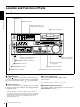
Location and Function of Parts Front Panel a POWER switch Chapter 1 Overview b Audio level meters A Input selection/audio mode display section (see page 9) c Cassette compartment POWER dB 0 OVER dB 0 dB 0 OVER dB 0 dB 0 OVER dB 0 dB 0 -12 1 -12 1 -12 1 -12 -20 0 -20 0 -20 0 -20 -30 -40 -60 -1 -2 -30 -40 1 -60 -1 -2 -30 -40 2 -60 -1 -2 -30 -40 3 -60 OVER dB INPUT V:SDTI SDTI i.
e HEADPHONES connector (stereo phone jack) Connect stereo headphones for headphone monitoring during recording or playback. The audio signal you want to monitor can be selected with the MONITOR SELECT switches on the menu control panel. g AUDIO INPUT LEVEL control knobs When recording, you can use these knobs to set audio input levels for CH-1 (channel 1), CH-2, CH-3 and CH-4, respectively. You can make these knobs inoperative with the REC LEVEL menu item (see page 64).
B Menu control panel The menu control panel is located on the inside of the door at the lower front of the unit. Pull the top of the door to open it.
b INPUT SELECT section CH1,1/2 (audio channel 1 or 1/2) button Each press of this button cycles through the following input audio signal selection options for audio channel 1 (when in 2-channel mode) or for audio channels 1 and 2 (when in 4-channel mode).
h TC (time code) PRESET button Use this button when setting an initial time code value and user bit data. respect to the reference video signal. Use a cross-point (Phillips) screwdriver to turn it. For details on setting time code and user bit data, see “Using the Internal Time Code Generator” on page 43. j SYNC (synchronization) PHASE control Turn this control to accurately adjust the synchronization phase of the output video signal of the unit with respect to the reference video signal.
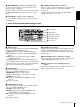
D Display section a Recording/playback format indicators b ClipLink indicator c VITC indicator Chapter 1 Overview d Time data type indicators e Time counter display i CHANNEL CONDITION indicators h SERVO indicator g Cassette memory indicator f REC INHIBIT indicator j REPEAT indicator k Tape end alarm indicator l SHUTTLE/JOG indicators m NOT EDITABLE indicator a Recording/playback format indicators DVCAM: This lights when a tape recorded in DVCAM format is played back.
c VITC indicator Lights when VITC is being read or recorded regardless of the data shown in the time counter display. Chapter 1 Overview d Time data type indicators One of the three indicators (COUNTER, U-BIT, and TC) lights to indicate the type of time data currently shown in the time counter display.
in the reverse direction. When the tape is stopped, the s indicator in the display section lights. Pressing this dial toggles playback between shuttle mode and jog mode. When playing back in shuttle mode, the SHUTTLE indicator in the display section lights, and when playing back in jog mode, the JOG indicator lights. You can carry out noiseless playback in the range of ±1/2 times normal speed.
Rear Panel A Analog video signal input/output section (see page 17) Chapter 1 Overview B Digital signal input/output section (see page 18) IN ANALOG VIDEO VIDEO IN LOW OFF LEVEL DIGITAL AUDIO(AES/EBU) OUT IN OUT IN CH-1/2 CH-3/4 OUT CH-1/2 CH-3/4 TIME CODE S VIDEO IN AUDIO IN SDI SDTI(QSDI) DV IN/OUT HIGH LOW ON OFF 600Ω LEVEL COMPONENT VIDEO IN Y HIGH LOW ON OFF 600Ω R-Y LEVEL REF.
A Analog video signal input/output section ANALOG VIDEO VIDEO IN S VIDEO IN COMPONENT VIDEO IN Y R-Y REF.VIDEO IN B-Y VIDEO OUT OUT 1 2 (SUPER) S VIDEO OUT Y d REF.
is used, the built-in 75 Ω termination switch turns off automatically. The REF. VIDEO OUT connector outputs a reference video signal, except when i.LINK is selected in the INPUT SELECT section (see page 11). g COMPONENT VIDEO OUT Y/R−Y/B−Y connectors (BNC type) These connectors output analog component video signals (Y/R−Y/B−Y). Chapter 1 Overview h TIME CODE IN/OUT connectors (BNC type) Input SMPTE time code (for DSR-1800) or EBU time code (for DSR-1800P) externally generated to the IN connector.
a DV IN/OUT connector (6-pin IEEE-1394) (optional DSBK-1803 i.LINK/DV Input/Output Board required) This i.LINK-compatible connector (subsequently referred to also as the i.DV IN/OUT connector) inputs and outputs digital video and audio signals in DV format. c SDI (Serial Digital Interface) IN (input) and active through output connectors (BNC type) (optional DSBK-1801 SDI/AES/EBU Input/Output Board required) Input digital video and audio signals in SDI format to the left-hand connector.
Settings of the AUDIO IN LEVEL/600 Ω switches Audio input Switch setting VIDEO CONTROL Chapter 1 Overview Level Impedance −60 dBu (microphone input) High impedance (about 20 kΩ) LOW-OFF (left position) +4/0/−3 a)/− −6 dBu (line audio input) High impedance (about 20 kΩ) HIGH-OFF (middle position) −6 dBm +4/0/−3 a)/− (line audio input) 600 Ω HIGH-ON (right position) a VIDEO CONTROL connector REMOTE a) Selectable on DSR-1800P only b AUDIO IN CH-1 (channel 1) to CH-4 connectors (XLR 3-pin, fema
Recording and Playback Chapter 2 Usable Cassettes This unit can use the DVCAM cassettes listed below. Model name Size PDV-64ME/94ME/124ME/184ME Standard size PDVM-12ME/22ME/32ME/40ME Mini size The numbers in each model name indicate the maximum recording/playback time (in minutes) for each model. For example, the PDV-184ME has a maximum recording/playback time of 184 minutes.
DVCAM cassettes The following figure illustrates the DVCAM cassettes. REC/SAVE switch For details of this switch, see “Preventing accidental erasure” on page 23 Mini size Standard size Chapter 2 Recording and Playback Cassette memory This memory is used to store ClipLink log data. For details of ClipLink log data, see the appendix “ClipLink Guide”(page 104).
Preventing accidental erasure Set the REC/SAVE switch on the cassette to SAVE to prevent accidental erasure of recorded contents. REC/SAVE switch Set to SAVE REC SAVE Inserting and Ejecting Cassettes Inserting a cassette This unit accepts three sizes of cassette: L (standard size), M (medium size: DVCPRO) and S (mini size). When inserting a cassette in the unit, make sure its tape window faces upward as shown in the following figure.
No double insertion of cassettes When you insert a cassette, the orange lock-out plate appears in the cassette compartment to prevent double insertion. Ejecting a cassette Press the EJECT button. dB 0 -12 -20 -30 -40 -60 Chapter 2 Recording and Playback 24 OVER dB 0 dB 0 1 -12 0 -20 -1 -2 -30 -40 1 -60 OVER dB 0 dB 0 1 -12 0 -20 -1 -2 -30 -40 2 -60 OVER dB 0 dB 0 1 -12 0 -20 -1 -2 -30 -40 3 -60 OVER dB INPUT V:SDTI SDTI i.
Recording This section describes the necessary settings and operations to perform recording on this unit. The same settings and operations apply whether you are using the unit as part of an editing system, for dubbing*, or as a stand-alone recorder. * For dubbing of SDTI (QSDI) format signals, use the AUTO FUNCTION menu item SDTI (QSDI) DUBBING (see page 69). For details, see “Digitally Dubbing Signals in DVCAM Format” on page 50.
1 Power on the video monitor, then set its input switches according to the signals input from this unit. 2 Set up the player to play back a tape. For details, refer to the operating instructions for the player. 3 Power on this unit by pressing on the 4 When the REMOTE button is not lit (the external editing control unit is not used), use the COUNTER SEL button to select the type of time data to be used. side of the POWER switch.
Audio input signal (input connector) Corresponding button in the INPUT SELECT section Lit indicator in the input selection/audio mode display section Analog signal (AUDIO IN CH-1 to CH4) CH-1,1/2 and CH-2,3/4 ANALOG in AUDIO group AES/EBU signal (DIGITAL AUDIO (AES/ EBU) IN) CH-1,1/2 and CH-2,3/4 AES/EBU a) in AUDIO group SDI signal (SDI IN) CH-1,1/2 and CH-2,3/4 SDI a) in AUDIO group SDTI (QSDI) signal (SDTI (QSDI) IN) SDTI/i.LINK SDTI a) i.
Recording Procedure This section describes the procedure to perform recording on this unit, showing an example session in which playback signals coming from a player VCR will be recorded on the tape loaded in the unit. 1 dB 0 OVER dB -20 -30 -40 -60 dB 0 0 -12 1 -12 0 -20 -1 -2 -30 -40 1 -60 OVER dB dB 0 0 1 -12 0 -20 -1 -2 -30 -40 2 -60 OVER dB dB 0 0 1 -12 0 -20 -1 -2 -30 -40 3 -60 OVER dB INPUT V:SDTI SDTI i.
1 After checking the following items, hold the cassette with the tape window facing upward, then insert it into the recorder (this unit) as illustrated on page 23. . Item to check See section Make sure that the REC/SAVE switch “Preventing accidental erasure” on of the cassette is set to REC. page 23 Check for tape slack. “Checking the tape for slack” on page 22 Make sure that the “HUMID!” alarm is “Condensation” on page 91 not shown in the time counter display.
If the following indicators light when a cassette is loaded Indicator It means: Cassette memory indicator The loaded cassette contains a cassette memory. ClipLink indicator There is ClipLink log data stored in the cassette memory on the loaded cassette. Caution With such a cassette, carrying out recording destroys the ClipLink log data. NOT EDITABLE indicator The recording format of the tape is “DV,” or a DVCPRO tape is inserted. Replace the tape with one that has been recorded in DVCAM format.
Playback This section describes the settings and operations necessary to perform playback on this unit. The same settings and operations apply whether you are using the unit as part of an editing system, for dubbing, or as a stand-alone player VCR. For the necessary connections for playback and the settings not covered in this section, see Chapter 5 “Connections and Settings.
Playback Procedure 1 dB 0 -12 -20 -30 -40 -60 OVER dB 0 dB 0 1 -12 0 -20 -1 -2 -30 -40 1 -60 OVER dB 0 dB 0 1 -12 0 -20 -1 -2 -30 -40 2 -60 OVER dB 0 dB 0 1 -12 0 -20 -1 -2 -30 -40 3 -60 OVER dB INPUT V:SDTI SDTI i.LINK 0 1 VIDEO 0 CH11/2 -1 AUDIO -2 4 CH23/4 PB FS COMPOSITE Y-R,B S VIDEO ANALOG AES/EBU ANALOG AES/EBU 48k44.
If the following indicators light when a cassette is loaded Indicator It means: Cassette memory indicator The loaded cassette contains a cassette memory. ClipLink indicator There is ClipLink log data stored in the cassette memory on the loaded cassette. NOT EDITABLE indicator The tape was recorded in the DV format, or a DVCPRO tape is inserted. You cannot use it as a recording tape for editing. To perform the following operations Do this: Stop playback. Press the STOP button.
Repeat Playback—Automatic Cyclical Playback Proceed as follows to perform automatic cyclical playback of recording (repeat playback) between selected start and end points. 1 Set the desired repeat start and end points with the REPEAT FUNCTION menu item (see page 56). You can set points A and B as start and end points by following the procedure described in the next section. 2 Set the REPEAT MODE menu item (see page 56) to ON. The REPEAT indicator lights.
While holding down the SET (YES) MARK button on the menu control panel, press the KA or Bk button. The time code value of the current tape position is set as point A or B, and a message “A set” or “B set” is displayed for 0.5 second in the time counter display. Once set, the point A or B time code value is held in the non-volatile memory of the unit until changed. It is not lost when the unit is powered off. Note When setting point A or B, you can only use a time code value.
2 With “SETUP MENU” selected, press the Bk button. The display changes as follows. SETUP MENU OPERATIONAL FUNCTION DISPLAY CONTROL TIME CODE SETUP BANK OPERATION MENU GRADE Operational Time counter display :BASIC Monitor screen Chapter 2 Recording and Playback 3 With “OPERATIONAL FUNCTION” selected, press the Bk button. The display changes as follows.
5 Press the j button to select “REPEAT TOP.” SETUP MENU OPERATIONAL FUNCTION REPEAT FUNCTION REPEAT MODE :OFF REPEAT TOP :T.TOP REPEAT END :V.END A PRESET B PRESET >> REP TOP Time counter display Monitor screen 6 Press the Bk button. Chapter 2 Recording and Playback The display changes as follows. SETUP MENU OPERATIONAL FUNCTION REPEAT FUNCTION :T.TOP REPEAT TOP * TAPE TOP :V.END A POINT >>> Tape top Time counter display Monitor screen 7 Press the j button to select “A POINT.
8 Press the KA button. The display changes as follows. SETUP MENU OPERATIONAL FUNCTION REPEAT FUNCTION :OFF REPEAT MODE .A REPEAT TOP :V.END REPEAT END A PRESET B PRESET >> REP TOP Time counter display Monitor screen Chapter 2 Recording and Playback 9 Press the j button to select “A PRESET.” SETUP MENU OPERATIONAL FUNCTION REPEAT FUNCTION :OFF REPEAT MODE .A REPEAT TOP :V.END REPEAT END A PRESET B PRESET >> A preset Time counter display Monitor screen 10Press the Bk button.
12Press the J or j button to increment or decrement the value of the flashing digit. Each press of the button increments or decrements the value. Holding the button down increments or decrements the value continuously. To change other digits, return to step 11. 13Press the SET (YES) MARK button to confirm the defined value. The message “NOW SAVING...” is displayed on the monitor screen and “Saving...” is shown in the time counter display while the new setting is being saved in memory.
Chapter 2 Recording and Playback Playback 40
Convenient Functions for Editing Operation Setting the Time Data This unit is provided with the following functions related to time data. • Display and reset CNT value • Set, display, record, and play back SMPTE/EBU time code and user bit data • Set, display, record, and play back VITC The unit can output the time code read from the tape as an analog (LTC) signal while in normal-speed playback mode, and receive an external analog time code (LTC) signal.
Monitor screen contents The contents of the monitor screen are shown below. C Drop frame indication for time code generator (for DSR-1800 only) . Drop frame mode (factory default setting) : Non-drop frame mode A Time data type Time data B Drop frame indication for time code reader a) C Drop frame indication for time code generator a) D VITC field indication 0 0 : 0 4 . 4 7 . 0 7 * T C R P L A Y L O C K E DSR-1800/1800P operation mode a) This character (.) can appear on the DSR-1800 only.
To display the desired time data in the time counter display To reset the CNT value Press the RESET (NO) button on the menu control panel. This resets the CNT value to 0:00:00:00. Note Time data type indicators During playback, if the recording on the tape includes discontinuities, the counter may operate incorrectly at the corresponding points.
2 Set the TIME CODE menu items (see page 60) as shown below. Menu item Setting TC MODE “INT PRESET” RUN MODE “FREE RUN” or “REC RUN” DF MODE Normally “ON (DF)” (for DSR-1800 only) 3 Press the TC PRESET button on the menu control panel. The current setting is shown on the monitor screen and in the time counter display on the front panel. The leftmost digit keeps flashing. One of the following menu screens is displayed on the monitor depending on the setting made in step 1.
Synchronizing Internal and External Time Codes Rerecording the Time Code—TC Insert Function The internal time code generator can be synchronized with an external time code (LTC) input to this unit. The TC insert function makes it possible to use the internal time code generator to rewrite time code or user bits when the time code recorded on a tape is discontinuous. You can start recording time code from an initial value which can be set freely (see page 43).
2 Press the J or j button to select “AUTO FUNCTION.” SYSTEM MENU SETUP MENU AUTO FUNCTION HOURS METER 5 Press the k button. The following message appears. Auto func TC INSERT Time counter display Set tape! Time counter display INSERT THE TAPE IN THIS VTR. ABORT:MENU KEY Monitor screen Monitor screen 3 Press the k button. 6 This displays the items in the level 1 of the auto mode execution menu. Chapter 3 Convenient Functions for Editing Operation AUTO FUNCTION MENU SDTI DUBBING i.
7 Press the SET (YES) button. Time code recording starts from the current tape position. TC INSERT Executing Time counter display EXECUTING. TCR 00:00:00:00 UBR 00:00:00:00 ABORT:MENU KEY Monitor screen When the recording ends, the message “TC INSERT COMPLETED. PUSH THE YES BUTTON.” appears on the monitor screen and “Completed” appears in the time counter display. Press the SET (YES) button to exit the menu.
High-Speed and LowSpeed Search—Quickly and Accurately Determining Editing Points Use the search function to easily locate the desired scene and to quickly and accurately determine edit points. When F. FWD/REW under the AUTO EE SELECT menu item (see page 57) is set to PB (factory default setting), you can use the F FWD and REW buttons on this unit or external equipment for high-speed search.
Search Operations on This Unit SHUTTLE indicator When you perform searching on this unit, be sure to turn off the REMOTE button on the front panel. dB 0 -12 -20 -30 -40 -60 OVER dB 0 dB 0 1 -12 0 -20 -1 -2 -30 -40 1 -60 OVER dB 0 dB 0 1 -12 0 -20 -1 -2 -30 -40 2 -60 OVER dB 0 dB 0 1 -12 0 -20 -1 -2 -30 -40 3 -60 OVER dB INPUT V:SDTI SDTI i.LINK 0 1 VIDEO 0 CH11/2 -1 AUDIO -2 4 CH23/4 PB FS COMPOSITE Y-R,B S VIDEO ANALOG AES/EBU ANALOG AES/EBU 48k44.
Use the following procedure. Digitally Dubbing Signals in DVCAM Format A In addition to straightforward tape dubbing, you can also use this unit to dub automatically from the beginning of the tape to the end through the SDTI (QSDI) or i.LINK interface. • To use the SDTI (QSDI) interface, the optional DSBK1802 board is required. • To use the i.LINK interface, the optional DSBK-1803 board is required.
3 6 Press the k button. This displays the items in the level 1 of the auto mode execution menu. AUTO FUNCTION MENU SDTI DUBBING i.LINK DUBBING TC INSERT Insert the source tape in the player, and the recording tape in this unit. A message to confirm the dubbing operation appears.
If the following message appears in step 6 for an A/V/TC/CM dubbing operation SDTI DUBBING (A/V/TC/CM) CM capacity! Time counter display CM MEMORY STORAGE CAPACITY OF THE RECORD TAPE IS TOO SMALL. ABORT:MENU KEY Monitor screen When carrying out A/V/TC/CM dubbing, if you insert the cassettes in step 6, the cassette memory capacity of the cassettes inserted in both this unit and the player are checked automatically.
Menu Settings Chapter 4 Menu Organization As shown in the following figure, the menu system consists of four levels and is functionally divided into three subsystems: the setup menu, the auto mode (AUTO FUNCTION) execution menu and the digital hours meter display menu. This chapter mainly describes the setup menu, showing its contents and how to operate it.
Menu organization Menu selection level SETUP MENU Level 1 OPERATIONAL FUNCTION Level 2 Level 3 REPEAT FUNCTION REPEAT MODE REPEAT TOP REPEAT END A PRESET B PRESET AUTO EE SELECT CASSETTE OUT F.FWD/REW STOP STANDBY OFF LOCAL ENABLE REC INHIBIT A1 EDIT CH A2 EDIT CH SEARCH ENABLE MAX SRCH SPEED SHUTTLE F.FWD/REW JOG RESPONSE PREROLL TIME AFTER CUE-UP PLAY START AUTO REW A MODE CHANGE Chapter 4 Menu Settings DISPLAY CONTROL CHARA. DISPLAY CHARA. POSITION CHARA. TYPE CHARA.
Menu selection level Level 1 Level 2 Level 3 (Continued) VIDEO CONTROL AUDIO CONTROL EE DELAY INT VIDEO SG STD/NON-STD OUT REF SEL SETUP REMOVE a) SETUP ADD a) CC(F1) BLANK a) CC(F2) BLANK a) WIDE MODE ESR MODE PROCESS CONTROL CONTROL DEV C PHASE MODE ADJ RANGE VIDEO GAIN CHROMA GAIN CHROMA PHASE SETUP LEVEL a) BLACK LEVEL b) INPUT BLANK b) LINE 335 REC MODE INPUT ARRANGE REC LEVEL LEVEL SELECT INT AUDIO SG OUTPUT CH3/4 OUTPUT PHASE JOG CONTROL SHUTTLE MUTE AUDIO EDIT DV PB ATT REF LEVEL CH1 IN L
Menu Contents Setup Menu Examples: The purpose and settings of the setup menu items are described below. Indications of menu items and settings • In the table below entitled “Menu contents,” the indication of each menu item or setting on the monitor screen is shown first, then the indication of the same item or setting in the time counter display of this unit is shown in square brackets ([ ]).
OPERATIONAL FUNCTION [Operational]: Operation settings Description of settings AUTO EE SELECT [> Auto EE]: CASSETTE OUT [>> Determine whether the unit Cass. out]: Operations enters EE mode or PB mode when the cassette has when audio and video been ejected signals from other equipment F. FWD/REW [>> F. FWD/ are input.
OPERATIONAL FUNCTION [Operational]: Operation settings Description of settings JOG RESPONSE [>JOG dial]: Select the tape speed *TYPE1 (-1 to +1) [>> type 1]: Tape speed varies linearly characteristics for the search dial rotation rate in jog mode. over the range −1 to +1. TYPE2 (-3 to +3) [>> type 2]: Tape speed varies stepwise as shown in the figure below over the range −3 to +3.
DISPLAY CONTROL [Display]: Settings related to indications on the monitor and the unit Description of settings CHARA. DISPLAY [> Chara disp]: Determine whether or not to output text (such as time code values) from the VIDEO OUT 2 (SUPER) connector. OFF [>> OFF]: Do not output text. (In spite of this setting, pressing the MENU button causes menu text to be output.) *ON [>> ON]: Output text. CHARA.
DISPLAY CONTROL [Display]: Settings related to indications on the monitor and the unit Description of settings PEAK HOLD [>Peak hold]: Set the peak hold time for the audio level meters. OFF [>> OFF] to 1.5 SEC [1.5 sec]: Set the peak hold time in the range of OFF (no peak hold) to 1.5 seconds in 0.1 second steps. Factory default setting: OFF [>> OFF] OVER DISP HOLD [> Hold OVER]: Determine whether or not *OFF [>> OFF]: Do not hold the OVER indication display.
TIME CODE [Time code]: Settings related to the time code Description of settings generator TC SELECT [>TC select]: Determine which to display in the time counter display, TC or VITC. VITC [>> VITC]: Display VITC. *TC [>> TC]: Display TC. VITC [> VITC]: Determine whether to record the internally generated time code as VITC. OFF [>> OFF]: Do not record the internally generated time code as VITC. (VITC present in the input video signal is recorded unchanged.
TAPE PROTECTION [Tape protct]: Settings related to tape and video head protection Description of settings FROM STOP [> From STOP]: STOP TIMER [>> STP Set the time to switch from timer]: Set the time to stop mode to tape protection switch from stop mode mode. to tape protection mode. 5 MIN [>>> 5 min] to 0.5 SEC [>>> 0.5 sec]: Select time from 12 settings ranging from 0.5 second to 5 minutes in steps of 0.1 second.
VIDEO CONTROL [Video]: Settings related to video control Description of settings WIDE MODE [>Wide mode]: Determine whether to retain wide-screen aspect ratio information accompanying video being recorded or played back. *AUTO [>> Auto]: When video being recorded or played back is accompanied by wide-screen aspect ratio information, retain the information. OFF [>> OFF]: Ignore wide-screen aspect ratio information.
AUDIO CONTROL [Audio]: Settings related to audio control Description of settings INPUT ARRANGE [>Input arng]: Make settings for input audio mixing. Make settings using the arrow buttons (KkJj) to move the cursor and the SET (YES) button to toggle the setting on and off. AUDIO INPUT SOURCE ARRANGE 1 in1 in2 in3 in4 ch1:*on ch2: on ch3: ch4 2 on @ @on on ON/OFF : TO MENU : 3 SET KEY MENU KEY 4 1 Input audio channel 1 (“in1”) is recorded on audio channel 1 (“ch1”) on tape.
AUDIO CONTROL [Audio]: Settings related to audio control Description of settings INT AUDIO SG [>Audio SG]: Select the operation of the internal audio test signal generator. SILENCE [>> silence]: Silent signal *1kHz SINE [>> 1kHz]: 1-kHz, −20 dB FS sine wave signal When you select SG as the audio input in the INPUT SELECT section on the front panel, the audio test signal generated by the internal audio test signal generator is input.
SETUP BANK OPERATION [Setup Bank]: Settings related to menu bank operations Description of settings RECALL BANK1 [>Recall 1]: Recall menu settings from menu bank 1. (1) Select the bank you want to recall, then press the k button. Message “RECALL OK?” appears. (2) To recall, press the SET (YES) button. To quit recalling, press the RESET (NO) button. RECALL BANK2 [>Recall 2]: Recall menu settings from menu bank 2. RECALL BANK3 [>Recall 3]: Recall menu settings from menu bank 3.
EE OUT PHASE settings for time code output Use the following as reference information when setting the EE OUT PHASE menu item (see page 61). • THROUGH mode In this mode, the LTC signal is output with the phase synchronized with the input time code signal. This mode is appropriate when recording signals from multiple devices on a number of VCRs. When the camcorder is in genlock mode, the time code precision is ±0 frames. When the camcorder is not in genlock mode, it is ±1 frame.
• VIDEO OUTPUT PHASE mode The time code output signal is synchronized with the output video signal. This mode is appropriate when outputting signals from a single device to a number of VCRs using separate cables for video, audio, and time code. In this mode, the same time code is recorded on all of the VCRs 1 to n. VIDEO OUT VIDEO IN AUDIO OUT VIDEO OUT AUDIO IN TIME CODE OUT AUDIO OUT TIME CODE IN Output device (VCR, camera, etc.
Auto Mode (AUTO FUNCTION) Execution Menu The following table shows the purpose and function of the items in the auto mode execution menu. For details of the use of individual items, see “Digitally Dubbing Signals in DVCAM Format” on page 50 and “Rerecording the Time Code—TC Insert Function” on page 45. Menu contents SDTI DUBBING [SDTI DUB]: Selection of data for SDTI dubbing Settings For dubbing through the SDTI (QSDI) interface, select data that A/V [> A/V]: Dub the audio and video.
Changing Menu Settings This section explains how to change menu settings. Changing the Settings of Basic Items The factory default setting is to display only the basic items. To change the settings of basic items proceed as follows. Buttons Used to Change Settings 1 3,5,7 2,4,6 Use the following buttons on the menu control panel to change the menu settings. Menu control buttons Functions MENU button • Opens the menu and launches menu control mode. • Closes the menu and exits menu control mode.
2 With “SETUP MENU” selected, press the k button. 5 This displays all items on menu level 1. Level-1 menu display SETUP MENU OPERATIONAL FUNCTION DISPLAY CONTROL TIME CODE SETUP BANK OPERATION MENU GRADE Operational Time counter display :BASIC Monitor screen 3 Press the J or j button to select the required item.
9 When you have completed the settings, press the SET (YES) button. Displaying Enhanced Items The message “NOW SAVING...” appears on the monitor screen, and “Saving...” appears in the time counter display, while the new settings are saved in memory. When the saving operation is completed, the monitor screen and time counter display return to their normal indications. The factory default setting is not to display enhanced items.
3 4 Follow the same procedure as in steps 3 to 8 of the procedure in the section “Changing the Settings of Basic Items” on page 70 using the arrow buttons to select an item and change its setting. When you have completed the settings, press the SET (YES) button. The message “NOW SAVING...” appears on the monitor screen, and “Saving...” appears in the time counter display, while the new settings are saved in memory.
Displaying Supplementary Status Information When you set the SUB STATUS menu item (see page 59) to other than OFF, you can view supplementary status information on the monitor screen below the operating mode display area. When the SUB STATUS menu item is set to TC MODE: On-screen indication Meaning INT PRESET FREE [IP F] The internal time code generator is operating in FREE RUN mode. INT PRESET REC [IP R] The internal time code generator is operating in REC RUN mode.
When the SUB STATUS menu item is set to AUDIO MIXING: On-screen indication Meaning 1234 [MIX] Input audio channels selected for mixing 1234: Input audio channels 1, 2, 3 and 4 Example display: 12 2 3 34 Input audio channels 3 and 4 are mixed and recorded on audio channel 4 on tape. Input audio channel 3 is recorded on audio channel 3 on tape. Input audio channel 2 is recorded on audio channel 2 on tape. Input audio channels 1 and 2 are mixed and recorded on audio channel 1 on tape.
Chapter 4 Menu Settings 76 Displaying Supplementary Status Information
Connections and Settings Chapter 5 Connections for a Digital Non-Linear Editing System This unit can be connected to an ES-7 EditStation to configure a digital non-linear editing system. If you use the SDTI (QSDI) interface with the optional DSBK-1802 board installed in the unit, you can transfer video, audio, time code, and other compressed data between this unit and the ES-7.
REF.
Connections for a Cut Editing System The following figure shows a cut editing system configuration that includes two DSR-1800/1800P units to serve as the player and recorder. When using a VCR other than the DSR-1800/1800P, refer to its instruction manual. When you select assemble or insert editing mode on the editing control unit, the two DSR-1800/1800P units (recorder and player) will automatically enter the selected editing mode.
Connections for an A/B Roll Editing System The following is an example configuration of A/B roll editing system using the DSR-1800/1800P. In this configuration, the recorder is a DSR-1800/1800P unit, player 1 is a DSR-1600/1600P unit, and player 2 is an analog Betacam UVW-1600/1600P Videocassette Player unit. To create a final tape (a tape that contains a completely packaged program) in Betacam format, use a Betacam VCR such as the UVW-1800/1800P as the recorder.
Main video monitor Source video monitor Audio system monitor Video signal generator (Sony Tektronix TSG130, etc.) DSR-1800/1800P (recorder) DPS-D7 or other delay unit a) MXP-290 Audio Mixer PVE-500, etc.
Audio monitor system connections Reference video signal connection The following shows an example of audio monitor system connections. When you perform recording, be sure to input a reference video signal. For details of these connections, refer to the instruction manual for each connected device. For details of reference video signals, see “About reference video signals” on page 79.
Control signal connections The following shows an example of control signal connections to enable the editing control unit to control all other A/B roll editing system devices.
Video/audio signal connections In this example, analog component signals are used as the video signals and XLR 3-pin connectors are used as audio input/output connectors. The following shows an example of video/audio signal connections in an A/B roll editing system.
Connection of a video monitor Settings on an editing control unit Set up the following connections to enable monitoring of video and audio signals on a video monitor. In addition to the video and audio signals, you can have time data, the operation mode of the unit, alarm messages, and other information displayed as text on the monitor screen by setting the CHARA. DISPLAY menu item (see page 59) to ON (factory default setting).
Connections for SDTI (QSDI) Dubbing The following shows an example of connections for digitally dubbing SDTI (QSDI) signals (see page 50), with the DSR-1800/1800P used as the recorder and a DSR1600/1600P unit as the player.
Connections for Analog Recording video signals are analog component signals and the audio signals are recorded from audio channels 1 and 2. The following shows connections for a system in which analog playback signals from another recorder or player are recorded on a DSR-1800/1800P. In this system, the Video monitor A Cable with RCA phono plugs (not supplied) B 75 Ω coaxial cable (not supplied) C Cable with XLR connectors (not supplied) Composite video input 2 Audio input 2 1 2 a) REF.
Adjusting the Sync and Subcarrier Phases After configuring the editing system, use a vectorscope to adjust the sync and subcarrier phases of the recorder and players. Subcarrier phase adjustment is necessary when using composite signals and Y/C signals. When using two or more players, as in an A/B roll editing system, it is necessary to synchronize the sync and subcarrier (for composite signals) phases of the signals to be edited.
Performing a phase adjustment operation Note 1 When component signals are used the subcarrier phase indicator does not appear. Press the SCH button on the vectorscope. The vectorscope switches to SCH mode. 2 8 Press the B channel button on the vectorscope. Output the player 2 signal from the PVE-500, and repeat steps 6 and 7 to adjust the sync and subcarrier phases of the output from player 2. This displays the black burst signal from the switcher. 3 Press the EXT button on the vectorscope.
Chapter 5 Connections and Settings 90 Adjusting the Sync and Subcarrier Phases
Maintenance and Troubleshooting Maintenance Chapter 6 Regular Checks Digital hours meter Condensation If you move the unit suddenly from a cold to a warm location, or if you use it in a very humid place, moisture from the air may condense on the head drum. This is called condensation, and if a tape is run in this state, the tape may stick to the drum and can be easily damaged. To lessen the risk of this occurring, this unit is equipped with a condensation detection system.
Displaying the digital hours meter Use the following procedure. 1 Press the MENU button on the menu control panel. The menu selection level display appears on the monitor screen and in the time counter display.
To end the digital hours meter display Press the MENU button on the menu control panel. To reset the trip values About this operation, consult your Sony dealer. Head Cleaning Always use the DVM12CL (mini size) or DV12CL (standard size) Cleaning Cassette to clean the video and audio heads. You can run the cleaning cassette for 10 seconds per cleaning operation. Follow the instructions for the cleaning cassette, as inappropriate use of the cleaning cassette can damage the heads.
Troubleshooting If an alarm message appears on the monitor screen, or if the unit appears to be malfunctioning, please check the following before contacting your Sony dealer. Tape problems Symptom Cause Recording is not possible. The cassette’s REC/SAVE switch is set Set the REC/SAVE switch to REC, or use another cassette. to SAVE. a) The unit’s tape transport control buttons (PLAY, F FWD, REW, etc.) do not work.
Monitor problems Symptom Cause Remedy Data is not superimposed on the monitor screen. The CHARA. DISPLAY menu item is set to OFF. Set the CHARA. DISPLAY menu item (see page 59) to ON. The monitor is not connected to the VIDEO OUT 2 (SUPER) connector of this unit. Connect the monitor to the VIDEO OUT 2 (SUPER) connector. (You must make this connection to display any type of text on the monitor.) The image on the monitor screen is too bright.
Error Messages This unit is provided with a self-diagnostic function that detects internal abnormalities. When it detects an abnormality, it outputs an error message to the monitor screen and indicates an error code in the time counter display. Note To display error messages on the monitor screen, connect the monitor to the VIDEO OUT 2 (SUPER) connector, and set the CHARA. DISPLAY menu item (see page 59) to ON (factory default setting). ERROR AN ERROR HAS BEEN DETECTED.
Alarm messages and associated directions Alarm message on monitor screen (Cause) Direction A cleaning tape has been inserted. The tape will automatically be ejected after cleaning is Cleaning Tp completed. A non-standard signal is being used for input video. Use a standard signal. VIN NON-STD A non-standard ref. signal is being used for REF. VIDEO. Use a standard signal. REF NON-STD Abnormal settings selected in setup menu. Correct the setup menu settings.
Alarm messages and associated directions Alarm message on monitor screen (Cause) Direction Alarm message in time counter display Tape cannot be replayed. Use a tape recorded in 525/60 format. (For DSR1800) 625/50 Tape (For DSR1800) Use a tape recorded in 625/50 format. (For DSR1800P) 525/60 Tape (For DSR1800P) Tape end has been detected. Use a new cleaning tape. Tape end! Tape not editable. Use a tape recorded in DVCAM format. Not DVCAM! Use a tape recorded in 525/60 format.
Appendixes Precautions On safety • Should any liquid or solid object fall into the cabinet, unplug the unit and have it checked by qualified personnel before operating it further. • Unplug the unit from the wall outlet if it is not to be used for an extended period of time. • To disconnect the cord, pull it out by the plug. Never pull the cord itself. On operation and storage locations Avoid operation or storage in any of the following places.
Specifications Dimensions (w/h/d, excluding projections) 427 × 174 × 400 mm (167/8 × 67/8 × 153/4 inches) General Appendixes 100 Specifications 320(12 5/8) 174(6 7/8) 34(1 3/8) 400(15 3/4) Signal system 372(14 3/4) 18(23/32) DSR-1800: NTSC DSR-1800P: PAL Power requirements 100 V to 240 V AC, 50/60 Hz Power consumption (with all options installed) DSR-1800: 100 W/120 V DSR-1800P for Europe: 100 W/220 V DSR-1800P for USA and Canada: 100 W/120 V Peak inrush current (1)Power ON, current probe metho
Video performance Input connectors Band width Digital signal inputs SDTI (QSDI) IN (with optional DSBK-1802 SDTI (QSDI) Input/Output Board installed) BNC type, SDTI (QSDI) format (270 Mbps) SDI IN (with optional DSBK-1801 SDI/AES/EBU Input/ Output Board installed) BNC type (×2, active-through), Serial Digital Interface format (270 Mbps), SMPTE 259M/CCIR656-III i.DV IN/OUT (with optional DSBK-1803 i.
Output connectors Digital signal outputs SDTI (QSDI) OUT (with optional DSBK-1802 SDTI (QSDI) Input/Output Board installed) BNC type, SDTI (QSDI) format (270 Mbps) SDI OUT (with optional DSBK-1801 SDI/AES/EBU Input/Output Board installed) BNC type (×2, active-through), Serial Digital Interface format (270 Mbps), SMPTE 259M/CCIR656-III i.DV IN/OUT (with optional DSBK-1803 i.LINK/DV Input/Output Board installed) 6-pin IEEE 1394 connector Analog video outputs REF. VIDEO OUT BNC type ×1 Black burst 0.
Related equipment ES-3/7 EditStation Linear editing control unit: PVE-500, RM-450/450CE, BVE-600/800/910/2000/9100/9100P DME switcher: DFS-300/300P, DFS-500/500P, DFS-700/700P DXC-D30/D30P Color Video Camera DSR-1/1P/300A Digital Videocassette Recorder DSR-85/85P/2000/2000P Digital Videocassette Recorder DSR-1600/1600P Digital Videocassette Player DSR-300/300P/500WS/500WSP/130/130P/150/150P Digital Camcorder DSRM-10 Remote Control Unit TBC remote control unit: UVR-60/60P, BVR-50/50P Design and specificatio
ClipLink Guide What Is ClipLink? The ClipLink function greatly improves the efficiency of the video production process as a whole by recording various editing-related data on tape when shooting. As such, ClipLink is a revolutionary function that transcends the conventional separation of shooting and editing. How ClipLink Changes Video Production Techniques The following describes various ways in which ClipLink* video production differs from conventional video production.
Example System Configuration and Operation Flow The following illustration shows an example system configuration for using the ClipLink function and a typical ClipLink operation flow. Shooting DVCAM standard cassette or DVCAM mini cassette DVCAM camcorder (DSR-130/130P/ 300/300P/500WS/ 500WSP) Index pictures: recorded on tape ClipLink log data: recorded in cassette memory ClipLink log data recorded onto DVCAM cassettes links shooting and editing operations.
ClipLink log data Data Generated When Shooting The following describes the kinds of data that is generated when using the ClipLink function. ClipLink log data can be recorded automatically or manually into the cassette memory for use as a convenient alternative to the conventional “shot list.” ClipLink log data includes the following items.
How to record ClipLink log data The following describes how to record the various ClipLink log data items. OK/NG status To designate a scene as “NG,” press the NG button on the camera while shooting the scene or at any time before you begin shooting the next scene. All scenes that do not receive an “NG” designation are recorded as “OK” scenes. (When you exit the VCR recording mode, changing the OK/NG status is no longer possible.
Time codes recorded for Mark IN/OUT points There is a gap between actual time codes and Mark IN/ OUT time codes recorded in the cassette memory, as shown in the figure below. The time code value is rounded up at each Mark IN point and rounded down at each Mark OUT point, to a whole number of seconds. Mark IN (or Rec IN) Actual time code 12:23:15:10 Cue 12:34:20:20 12:23:16 (The index picture is the image around 12:23:15:10.
Glossary A/B roll editing An editing method that uses two or more playback VCRs to create special effects such as dissolve and wipe, and uses one record VCR to record the results of the editing. Using an editing control unit allows efficient control of the VCRs and very precise editing. Drop frame mode Time code runs at 30 frames/sec. The NTSC system, however, runs at about 29.97 frames/sec. Drop frame mode adjusts this difference.
S/N Abbreviation of Signal-to-Noise (ratio). The higher the S/N value, the less noise and higher the picture quality. Search mode A VCR operating mode used when searching for specific scenes, by viewing the video output or time code values while playing back the tape at various speeds in forward or reverse direction.
Index Numerics 9PIN button 15 A/B roll editing system 80 AC IN connector 16 Alarm messages 96 Analog audio signal input/output section 19 Analog interfaces 6 Analog recording 87 Analog video signal input/output section 17 Arrow buttons 11 Aspect ratio 7 AUDIO CH1 1/2 display 9 AUDIO CH2 3/4 display 9 AUDIO IN CH-1 to CH-4 connectors 20 AUDIO IN LEVEL/600-ohm switches 19 AUDIO INPUT LEVEL control knobs 9 Audio level meters 8 AUDIO MONITOR OUT connector 20 Audio monitor system connections 82 AUDIO OUT CH-1 t
item indications 56 MENU button 11 Menu control panel 10 MONITOR SELECT switches 10 N Non-linear editing 5, 77 NOT EDITABLE indicator 14 Index O OK/NG status 107 Operation mode indications 41, 42 Optional accessories 102 P PB FS display 9 PCM digital audio 5 Phases adjustment 88 PHONE LEVEL control knob 8 PLAY button 12 Playback 49 Playback modes 15 jog mode 49 shuttle mode 49 POWER switch 8 Precautions 99 Processor adjustment range 101 R Rack mount 7 Rear panel 16 REC button 12 REC INHIBIT indicator 14
Sony Corporation Printed in Japan