4-130-031-11(3) Home Theatre System Operating Instructions HT-SF360 HT-SS360 ©2009 Sony Corporation
For customers in Australia WARNING To reduce the risk of fire or electric shock, do not expose this apparatus to rain or moisture. To reduce the risk of fire, do not cover the ventilation opening of the apparatus with newspapers, tablecloths, curtain, etc. Do not place the naked flame sources such as lighted candles on the apparatus.
Disposal of waste batteries (applicable in the European Union and other European countries with separate collection systems) This symbol on the battery or on the packaging indicates that the battery provided with this product shall not be treated as household waste. On certain batteries this symbol might be used in combination with a chemical symbol. The chemical symbols for mercury (Hg) or lead (Pb) are added if the battery contains more than 0.0005% mercury or 0.004% lead.
On Copyrights About This Manual • The instructions in this manual are for model HT-SF360 and HT-SS360. • In this manual, models of area code CEL is used for illustration purposes unless stated otherwise. Any difference in operation is clearly indicated in the text, for example, “Models of area code AU only”.
Table of Contents Description and location of parts .................. 6 Tuner Operations Getting Started 1: Installing the speakers............................. 13 2: Connecting the speakers ......................... 15 3: Connecting the TV .................................. 16 4: Connecting the audio/video components 17 5: Connecting the antennas ......................... 21 6: Preparing the receiver and the remote..... 22 7: Calibrating the appropriate settings automatically (AUTO CALIBRATION) .........
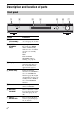
Description and location of parts Front panel 1 2 3 4 5 6 7 INPUT SELECTOR ?/1 MASTER VOLUME ACTIVE STANDBY Name Function A ?/1 (on/standby) Press to turn the receiver on or off (page 22, 29, 30). B ACTIVE STANDBY lamp Lights up in amber when the Control for HDMI and/or S-AIR standby mode are set to on and the receiver is on standby mode. Note If the ACTIVE STANDBY lamp is flashing, see page 68.
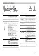
Indicators on the display 12 3 qd 4 qs 5 6 7 8 qa q; 9 Name Function Name Function A LFE Lights up when the disc being played back contains an LFE (Low Frequency Effect) channel and the LFE channel signal is actually being reproduced. F HDMI Lights up when a playback component is connected to this receiver using an HDMI jack (page 19). B SLEEP Lights up when the sleep timer is activated (page 51). G Preset station indicators C Playback channel indicators The letters (L, C, R, etc.
Rear panel 1 2 34 5 L L R R 6 7 TV DIGITAL ANTENNA EZW-T100 AM AUTO AUDIO IN AUDIO IN AUDIO IN SA-CD/CD CAL MIC VIDEO 1 TV SPEAKERS DC5V COAX IN OPT IN VIDEO 2 SAT OPT IN 700mA MAX HDMI FRONT R FRONT L SUR R SUR L CENTER SUBWOOFER A SPEAKERS section BD IN B S-AIR (EZW-T100) CAUTION Please do not remove the slot cover until you want to install the wireless transmitter. HDMI IN/ OUT jacks C DMPORT DMPORT jack Connects to a DIGITAL MEDIA PORT adapter (page 18).
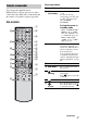
Basic operations Remote commander Remote Button Function You can use the supplied remote RM-AAU058 to operate the receiver and to control the Sony audio/video components that the remote is assigned to operate (page 60). B ?/1 (on/standby) RM-AAU058 Saving the power in standby mode 1 TV ?/1 DMPORT AV ?/1 ?/1 – When “CONTROL FOR HDMI” is set to “CTRL ON” and “P.SAVE” is set to “SAVE ON” (page 35). – When S-AIR standby “STBY” is set to “STBY OFF” (page 59).
Tuner operations Common operations Remote Button Function Remote Button Function H ENTER Press to enter the selection. M MENU/HOME Press to display the menu. A TV ?/1 AV ?/1 (on/standby) N PRESET +/– Press to select a preset station. Press to turn on or off the Sony audio/video components that the remote is assigned to operate (page 60). Press A ?/1 and B TV ?/1/AV ?/1 at the same time to turn off the receiver and all other components that the remote is assigned to operate (SYSTEM STANDBY).
Remote Button Function Remote Button Function J TOOLS/ OPTIONS Press to enable you to access various viewing options and change/make adjustments according to the source and screen format. V K Press to turn off the sound. (Muting) L +*/– M MENU/HOME N TV CH +/– c/C P RETURN/ EXIT Q , V/v/B/b R DISPLAY / (Info/Text reveal) S / (Text) Press to adjust the volume. Press to allow you to select channels or input sources and change the settings for your TV.
To control the DVD player/Blu-ray Disc player To control the SAT Remote Button Function F Remote Button Function Press to display the guide menu. M MENU/HOME Press to display the menu. N ./> Press to skip chapters. M MENU/HOME Press to display the menu. Press to jump backward. Q Press to select a menu item and enters the selection. < < m/M Press to jump forward. Press to fast reverse or to fast forward the disc when pressed during playback. H* (playback)/ Play mode button.
HT-SS360 only Getting Started Getting Started 1: Installing the speakers This receiver allows you to use a 5.1 channel speaker system. To fully enjoy theater-like multi channel surround sound, be sure to connect all the speakers (two front speakers, a center speaker, and two surround speakers) and a subwoofer (5.1 channel). You can place your speakers as shown below.
Installing the speakers on a flat surface Installing the speakers on the wall Before you install the speaker and subwoofer, be sure to attach the supplied foot pads to prevent vibration or movement as shown in the illustration below. You can install your speakers on the wall. 1 Example of HT-SS360 front speaker Prepare screws (not supplied) that are suitable for the hook on the back of each speaker. See the illustrations below. 4 mm more than 25 mm 4.
For the surround speakers of HT-SF360 Before connecting the cords, be sure to disconnect the AC power cord (mains lead). C B F For the front and surround speakers of HT-SS360 A 5 mm to 7 mm 3 Hang the speakers on the screws. SPEAKERS 4.6 mm FRONT R FRONT L SUR R SUR L CENTER SUBWOOFER 10 mm Connector A A Rear of speaker A D E Notes • Use screws that are suitable for the wall material and strength.
Note on speaker cords The connector of the speaker cords are the same color as the speaker jack to be connected. When connecting a speaker cord, be sure to match the colored connector to the speaker jack on the receiver: Connector Speaker jack Red FRONT R White FRONT L Grey SUR R Blue SUR L Green CENTER Purple SUBWOOFER 3: Connecting the TV You can watch the selected input image when you connect the HDMI OUT jack to a TV. It is not necessary to connect all the cords.
Tips 4: Connecting the audio/ video components How to hook up your components This section describes how to hook up your components to this receiver. Before you begin, refer to “Component to be connected” below for the pages which describe how to connect the audio/video components. Before connecting the cords, be sure to disconnect the AC power cord (mains lead). After hooking up all your components, proceed to “5: Connecting the antennas” (page 21).
Connecting audio components The following illustration shows how to connect audio components such as Super Audio CD player, CD player and DIGITAL MEDIA PORT adapter. You can also view the images on the TV screen by connecting the video output of the DIGITAL MEDIA PORT adapter to the video input of the TV. Super Audio CD player, CD player Audio signal A Notes on connecting DIGITAL MEDIA PORT adapter • Do not connect or disconnect the DIGITAL MEDIA PORT adapter while the receiver is turned on.
Connecting components with HDMI jacks TV, etc. By connecting Sony “BRAVIA” Sync compatible components using HDMI cables, ““BRAVIA” Sync Features” makes operations simpler (page 45).
Notes on HDMI connections • An audio signal input to the HDMI IN jack is output from the SPEAKERS jacks and HDMI OUT jack. It is not output from any other audio jacks. • Video signals input to the HDMI IN jack can only be output from the HDMI OUT jack. • The multi/stereo area audio signals of a Super Audio CD are not output. • Audio signals (sampling frequency, bit length, etc.) transmitted from an HDMI jack may be suppressed by the connected component.
Notes 5: Connecting the antennas Connect the supplied AM loop antenna and FM wire antenna. Before connecting the antennas, be sure to disconnect the AC power cord (mains lead). FM wire antenna (supplied) AM loop antenna (supplied) Tip All the digital audio jacks are compatible with 32 kHz, 44.1 kHz, 48 kHz, and 96 kHz sampling frequencies.
6: Preparing the receiver and the remote Connecting the AC power cord (mains lead) Inserting batteries into the remote Insert two R6 (size-AA) batteries in the RM-AAU058 Remote Commander. Observe the correct polarity when installing batteries. Connect the AC power cord (mains lead) to a wall outlet.
(AUTO CALIBRATION) This receiver is equipped with DCAC (Digital Cinema Auto Calibration) Technology which allows you to perform automatic calibration as follows: • Check the connection between each speaker and the receiver. • Adjust the speaker level. • Measure the distance of each speaker from your listening position. • Measure the frequency characteristics.* * The measurement result is not utilized for signals with a sampling frequency of more than 96 kHz.
Example: HT-SS360 L L R R Performing Auto Calibration TV DIGITAL ANTENNA EZW-T100 AM AUTO AUDIO IN AUDIO IN AUDIO IN SA-CD/CD CAL MIC VIDEO 1 TV SPEAKERS DC5V COAX IN OPT IN VIDEO 2 SAT OPT IN 700mA MAX HDMI FRONT R FRONT L SUR R SUR L CENTER SUBWOOFER DMPORT BD IN DVD IN SAT IN Optimizer microphone OUT TV ?/1 DMPORT AV ?/1 ?/1 ?/1 switch SYSTEM STANDBY VIDEO1 VIDEO2 SAT TV BD DVD SA-CD/CD TUNER BD/DVD TOP MENU MENU F1 F2 AUDIO THEATRE DIGITAL ANALOG 1 2 3 4 5
2 Notes Press V/v repeatedly to select the item. Then, press . Item Explanation SAVE Saves the measurement results and exits the setting process. WRN CHK Displays warning concerning the measurement results. See “When you select “WRN CHK”” (page 26). DIST Displays the measurement result for speaker distance. LEVEL Displays the measurement result for speaker level. EXIT Exits the setting process without saving the measurement results.
Error code Cause and remedies ERROR SW 33 The subwoofer may be damaged. Contact your Sony dealer or local authorized Sony service facility. When you select “WRN CHK” If a warning on the measurement result is present, detailed information is displayed. Press or B to return to step 2 of “Confirming/saving the measurement results”. Warning code Explanation WARN 40 The Auto Calibration has completed. However, the noise level is high.
8: Adjusting the speaker levels (TEST TONE) You can adjust the speaker levels while listening to the test tone from your listening position. AMP MENU CLEAR DISPLAY 0 ENTER AMP MENU TOOLS/ OPTIONS 7 , V,v,B,b 2 +/– RETURN/EXIT 1 Notes • “CNT LVL” does not appear when you set “CNT N” in the “SP SETUP” setting. • “SR LVL” and “SL LVL” do not appear when you set “SUR N” in the “SP SETUP” setting. MENU/HOME You can adjust from –6.0 dB to +6.0 dB in 0.5 dB steps. Press AMP MENU.
Playback Selecting a component TV ?/1 DMPORT AV ?/1 ?/1 SYSTEM STANDBY VIDEO1 VIDEO2 SAT TV BD/DVD TOP MENU MENU BD DVD SA-CD/CD TUNER F1 Input buttons F2 AUDIO THEATRE DIGITAL ANALOG 1 2 4 5 6 7 8 9 CLEAR 0 ENTER Selected input [Display] Components that can be played back DMPORT [DMPORT] DIGITAL MEDIA PORT adapter connected to the DMPORT jack VIDEO1 or VIDEO2 [VIDEO 1 or VIDEO 2] VCR, etc., connected to the VIDEO 1 or VIDEO 2 jack BD [BD] Blu-ray disc player, etc.
Tips Enjoying sound/images from the components connected to the receiver ?/1 ?/1 SYSTEM STANDBY Input buttons VIDEO1 VIDEO2 SAT TV BD DVD SA-CD/CD TUNER BD/DVD TOP MENU MENU F1 Enjoying a satellite tuner F2 AUDIO THEATRE DIGITAL ANALOG 1 2 3 4 5 6 7 8 9 CLEAR 0 ENTER SOUND FIELD 1 SOUND FIELD AMP MENU DISPLAY For details, refer to the operating instructions of the TV. 2 Turn the satellite tuner and the receiver on. 3 Press SAT.
Enjoying Blu-ray Disc or DVD 1 2 3 Turn on the Blu-ray Disc or DVD player (recorder) and the receiver. Press DVD or BD. 5 6 Play back the disc. Adjust the volume. Tip Even if you playback Dolby True HD, Dolby Digital Plus or DTS-HD with a connected component compatible with these sound formats, the receiver accepts as Dolby Digital or DTS.
To return to the previous display Amplifier Operations Press B. Navigating through menus To exit the menu Press AMP MENU. By using the amplifier menus, you can make various adjustments to customize the receiver. 8 9 CLEAR 0 ENTER Amplifier Operations 7 SOUND FIELD AMP MENU AMP MENU TOOLS/ OPTIONS DISPLAY , V,v,B,b RETURN/EXIT 1 MENU/HOME Press AMP MENU. “SET HDMI” appears on the display. 2 Press V/v repeatedly to select the menu you want. 3 Press menu.
Overview of the menus The following options are available in each menu. For details on navigating through menus, see page 31. Menu [Display] Parameters [Display] Settings Initial setting HDMI settings [SET HDMI] (page 35) Control for HDMIa)b) [CONTROL FOR HDMI] CTRL ON, CTRL OFF CTRL ON Volume limita) [VOL LIM] MAX, 39……1, MIN MAX Power savea) [P.SAVE] SAVE ON, SAVE OFF SAVE ON Auto Calibration settings [A.
Parameters [Display] Settings Initial setting Level settings [LEVEL] (page 37) Test tonea) [T. TONE] T. TONE N, T. TONE Y T. TONE N Front left speaker levela) [FL LVL] FL –6 dB to FL +6 dB (0.5 dB step) FL 0.0 dB Center speaker level [CNT LVL] CNT –6 dB to CNT +6 dB (0.5 dB step) CNT 0.0 dB Front right speaker level [FR LVL] FR –6 dB to FR +6 dB (0.5 dB step) FR 0.0 dB Surround right speaker level [SR LVL] SR –6 dB to SR +6 dB (0.5 dB step) SR 0.
Menu [Display] Parameters [Display] Settings Initial setting S-AIR settings [S-AIR] (page 52) S-AIR IDf) [S-AIR ID] ID A, ID B, ID C ID A PAIRINGf) [PAIRING] START, CONDIN START S-AIR modef) [MODE] PARTY, SEPARATE PARTY RF Changef) [RF CHNG] RF AUTO, RF ON, RF OFF RF AUTO RF Powerf)g) [RF POWER] PWR HIGH, PWR LOW PWR HIGH S-AIR standbyf) [STBY] STBY ON, STBY OFF STBY OFF a) For details, refer to the page in the parentheses. FOR HDMI” scroll across the display, then “CONTROL” appears.
Settings for the HDMI (SET HDMI menu) (A.CAL menu) SET HDMI menu parameters You can use the A.CAL menu to make settings for the Auto Calibration function to suit your preference. Select “A.CAL” in the amplifier menus. For details on adjusting the parameters, see “Navigating through menus” (page 31) and “Overview of the menus” (page 32). x CONTROL FOR HDMI (Control for HDMI) A.CAL menu parameters Lets you turn the Control for HDMI function on or off.
Settings for the Speaker x SR DIST (Surround right speaker distance) (SP SETUP menu) x SL DIST (Surround left speaker distance) You can use the SP SETUP menu to set the distance of the speakers connected to this receiver. Select “SP SETUP” in the amplifier menus. For details on adjusting the parameters, see “Navigating through menus” (page 31) and “Overview of the menus” (page 32). Lets you set the distance from your listening position to the surround speakers.
Adjusting the tone (LEVEL menu) (TONE menu) You can use the LEVEL menu to adjust the level of each speaker. Select “LEVEL” in the amplifier menus. For details on adjusting the parameters, see “Navigating through menus” (page 31) and “Overview of the menus” (page 32). You can use the TONE menu to adjust the tonal quality (bass/treble level) of the speakers. Select “TONE” in the amplifier menus.
Settings for the Custom Menu (CUSTOM menu) You can use the CUSTOM menu to make settings for the audio to suit your preference. Select “CUSTOM” in the amplifier menus. For details on adjusting the parameters, see “Navigating through menus” (page 31) and “Overview of the menus” (page 32). CUSTOM menu parameters x AUD. DRC (Audio dynamic range compression) Lets you compress the dynamic range of the sound track. This may be useful when you want to watch movies at low volumes late at night.
x IN MODE (Switching the audio input mode) Lets you set the audio input mode of inputs. For details, see “Switching the audio input mode (IN MODE)” (page 51). This parameter is only available when SAT input is selected. Settings for the S-AIR (S-AIR menu) For details on S-AIR, see “Using an S-AIR Product” (page 52).
Enjoying Surround Sound 4 5 6 7 8 9 SOUND FIELD SOUND FIELD AMP MENU Selecting the sound field CLEAR 0 ENTER Press SOUND FIELD repeatedly to select the sound field you want. This receiver can create multi channel surround sound. You can select one of the optimized sound fields from the receiver’s preprogrammed sound fields. For details, see “Types of sound field available” (page 40). Types of sound field available Sound field for Sound field [Display] Effect A.F.D.
Notes Tuner Operations Listening to FM/AM radio You can listen to FM and AM broadcasts through the built-in tuner. Before operation, make sure you have connected the FM and AM antennas to the receiver (page 21). Tip The tuning scale for direct tuning differs depending on the area code as shown in the following table. For details on area codes, see page 4. Area code FM AM AU, SP, TW, TH, CN 50 kHz 9 kHz* CEL, CEK 50 kHz 9 kHz * The AM tuning scale can be changed (page 43).
1 Press TUNER repeatedly to select the FM or AM band. You can also use INPUT SELECTOR on the receiver. 2 Press TUNING + or TUNING –. Press TUNING + to scan from low to high; press TUNING – to scan from high to low. The receiver stops scanning whenever a station is received. To stop the automatic tuning manually, press TUNING + or –. Presetting radio stations You can preset up to 20 FM stations and 10 AM stations. Then you can easily tune in the stations you often listen to.
5 or b. Press A preset number appears in the display. 6 Press V/v repeatedly to select the preset number you want. You can select the preset number directly by pressing the number buttons. 7 Press Tuning to preset stations 1 Press TUNER repeatedly to select the FM or AM band. 2 Press PRESET + or PRESET – repeatedly to select the preset station you want. . Each time you press the button, the receiver tunes in one preset station.
If you enter a wrong character Press B/b repeatedly until the character to be changed flashes, then press V/v repeatedly to select the desired character. To erase the character, press B/b repeatedly until the character to be erased flashes, then press CLEAR. 7 Press . “COMPLETE” appears in the display and the station name is stored. 8 Press MENU/HOME.
Using “BRAVIA” Sync features What is “BRAVIA” Sync? To use the “BRAVIA” Sync, set the Control for HDMI function to on for both the receiver and the connected component. The receiver is compatible with the “Control for HDMI-Easy Setting” function.
When your TV is not compatible with the “Control for HDMI-Easy Setting” function Turn the Control for HDMI function of the receiver and the connected component on individually. 7 8 9 CLEAR 0 ENTER SOUND FIELD AMP MENU DISPLAY AMP MENU TOOLS/ OPTIONS , V,v,B,b RETURN/EXIT MENU/HOME 1 Perform the steps given in “When your TV is compatible with the “Control for HDMI-Easy Setting” function” (page 45). 2 Press AMP MENU. “SET HDMI” appears on the display. 3 Press or b to enter the menu.
Playing back components with one-touch operation (One-Touch Play) You can enjoy sound and image from the components connected to the receiver via HDMI connections by a simple operation. Play back a connected component. The receiver and the TV are turned on automatically and switched to the appropriate HDMI input. Note Be sure that the System Audio Control setting is set to on. Watching a DVD/Blu-ray disc by simple operation Note Depending on the TV, the start of the content may not be output.
Using the Volume Limit function When the System Audio Control function is active, and the output method changes from the TV speaker to the speakers connected to the receiver automatically, loud sound may be output depending on the volume level of the receiver. You can prevent this by limiting the maximum volume level. 1 2 3 4 Press AMP MENU. Press v/V repeatedly until “SET HDMI” appears, then press or b.
Notes Using the Power Saving function (Power Save) You can reduce the receiver’s power consumption when you connect a “BRAVIA” Sync-compatible TV to this receiver during active standby mode if the TV is turned off and HDMI signal transmission is stopped. 4 5 6 7 8 9 CLEAR 0 ENTER • The power saving function may not work for some TVs compatible with the “BRAVIA” Sync. In this case, set “P.SAVE” to “SAVE OFF.” • Depending on your components, it may take time before image or sound is output.
Other Operations Changing the brightness of the display (DIMMER) Changing the display setting (DISPLAY) You can change the display setting. 1 You can change the brightness of the display. 1 “SET HDMI” appears on the display. 2 Press V/v repeatedly until “CUSTOM” appears, then press or b. Press V/v repeatedly until “CUSTOM” appears, then press or b. 3 Press V/v repeatedly until “DIMMER” appears, then press or b. Press V/v repeatedly until “DISPLAY” appears, then press or b.
Using the Sleep Timer (SLEEP) You can set the receiver to turn off at a preset time when you sleep while listening to music. You can preset the time in 10 minutes decrements. 1 Press AMP MENU. “SET HDMI” appears on the display. 2 3 4 (IN MODE) You can select the audio input mode setting when you connect satellite tuner or set-top box to both HDMI IN jack and optical digital input jack on the receiver and SAT input has been selected. 1 Press AMP MENU. “SET HDMI” appears on the display.
Using an S-AIR Product This receiver is compatible with the S-AIR function (page 62), which allows wireless sound transmission between S-AIR products. When you purchase the S-AIR product, you need to perform the following settings to establish the sound transmission. Room B S-AIR sub unit (S-AIR receiver) Room A S-AIR main unit (this receiver) INPUT SELECTOR ?/1 MASTER VOLUME ACTIVE STANDBY About S-AIR products There are two types of S-AIR product.
To insert the wireless transmitter into the S-AIR main unit 1 Remove the screws and detach the slot cover. Notes • Insert the wireless transmitter with the S-AIR logo facing up. • Insert the wireless transmitter so that the V marks are aligned. • Do not insert other than the wireless transmitter into the EZW-T100 slot. 3 Use the screws that you removed from Slot cover step 1 to fasten the wireless transmitter.
Establishing sound transmission between the S-AIR main unit and S-AIR sub unit (ID setting) When you match the ID of the S-AIR main unit and the S-AIR sub unit, you can establish sound transmission. You can use multiple S-AIR products by setting a different ID for each unit. 4 7 8 SOUND FIELD 9 AMP MENU CLEAR 0 For details on setting the ID of the surround amplifier and S-AIR receiver, refer to operating instructions supplied with the surround amplifier and S-AIR receiver.
2 x Before pairing Sound transmission is established by the ID (example). Your room • To set the ID of the S-AIR main unit, see “To set the ID of the S-AIR main unit” (page 54). • To set the ID of the S-AIR sub unit, refer to the operating instructions supplied with the S-AIR sub unit.
1 Note Perform the pairing within several minutes after step 8. Otherwise, the pairing is canceled automatically and the “INCOMP” display appears. • To set the ID of the S-AIR main unit, see “To set the ID of the S-AIR main unit” (page 54). • To set the ID of the S-AIR receiver, refer to the operating instructions supplied with S-AIR receiver. To cancel pairing Reset the ID of the S-AIR main unit. For details, see “To set the ID of the S-AIR main unit” (page 54). You can set the same ID as before.
7 Press V/v repeatedly to select the setting you want. • PARTY: The S-AIR sub unit outputs sound according to function set on the S-AIR main unit. • SEPARATE: You can select the input you want for the S-AIR receiver while the input of the S-AIR main unit remain unchanged. When “SEPARATE” is set, the functions you can select are “MAIN UNIT”, “SACD/CD”, “TUNER FM”, “TUNER AM” and “DMPORT”. To enjoy the same function as the S-AIR main unit, select “MAIN UNIT”.
6 Press V/v repeatedly to select the setting you want, then press . • RF AUTO: Normally select this. The system change “RF CHNG” to “RF ON” or “RF OFF” automatically. • RF ON: The system transmits sound by searching the better channel for transmitting. • RF OFF: The system transmits sound by fixing the channel for transmitting. To exit the menu Press AMP MENU. Changing the RF output power (For EZW-T100A wireless transceiver only) 1 2 Press AMP MENU. 3 Press menu.
Enjoying the S-AIR receiver while the S-AIR main unit is in standby mode (For the S-AIR receiver only (not supplied)) You can enjoy the S-AIR receiver while the S-AIR main unit is in standby mode by setting “STBY” to “STBY ON”. 4 5 6 7 8 9 CLEAR 0 SOUND FIELD AMP MENU ENTER AMP MENU TOOLS/ OPTIONS DISPLAY To exit the menu Press AMP MENU. Notes • When you set “STBY” to “STBY ON”, the power consumption increases during the standby mode.
2 Using the Remote Changing the input button assignments You can change the factory settings of the input buttons to suit the components in your system. For example, if you connect a Blu-ray Disc player to the DVD jack on the receiver, you can set the DVD button on this remote to control the Blu-ray Disc player. You cannot assign any component other than a TV to the TV (white) button of the remote. Notes • You can change the remote assignments for BD, DVD and SAT input buttons.
Categories and the corresponding buttons for TV Categories Press TV d) 5 TV e) 6 d) The default setting of the TV (white) button. When this setting is selected, the audio input of the TV is switched and the image from the TV tuner is displayed on the TV screen automatically by pressing the TV (white) button. e) When this setting is selected, the audio input of the TV is switched automatically by pressing the TV (white) button.
x DTS Digital Surround Digital audio encoding/decoding technology for theaters developed by DTS, Inc. It compresses audio less than Dolby Digital, delivering a higher quality sound reproduction. x HDMI (High-Definition Multimedia Interface) HDMI (High-Definition Multimedia Interface) is an interface that supports both video and audio on a single digital connection, allowing you to enjoy high quality digital picture and sound.
On placement Precautions On safety Should any solid object or liquid fall into the cabinet, unplug the receiver and have it checked by qualified personnel before operating it any further. On power sources • Before operating the receiver, check that the operating voltage is identical with your local power supply. The operating voltage is indicated on the nameplate on the back of the receiver.
If color irregularity is observed again... Place the speaker further away from the TV set. If howling occurs Reposition the speakers or turn down the volume on the receiver. Troubleshooting If you experience any of the following difficulties while using the receiver, use this troubleshooting guide to help you remedy the problem. Audio On cleaning Clean the cabinet, panel, and controls with a soft cloth slightly moistened with a mild detergent solution.
There is no sound from digital sources (from OPTICAL input jack). • Check that the IN MODE is set to “AUTO” for SAT input. There is severe hum or noise. • Check that the speakers and components are connected securely. • Check that the connecting cords are away from a transformer or motor, and at least 3 meters away from a TV set or fluorescent light. • Move your audio components away from the TV. • The plugs and jacks are dirty. Wipe them with a cloth slightly moistened with alcohol.
HDMI The volume turns down when the output method changes from the TV speaker to the speakers connected to the receiver. • The Volume Limit function is working. For details, see “Using the Volume Limit function” (page 48). The source sound input to the HDMI jack on the receiver is not output from the receiver or the TV speaker. • Check the setting of CONTROL FOR HDMI in the SET HDMI menu (page 35). • Check the HDMI connection (page 19). • You cannot listen to the Super Audio CD by connecting HDMI.
S-AIR function S-AIR connection is not established (sound transmission is not established), e.g., the indicator of the S-AIR sub unit turns off, flashes, or turns red. • If you use another S-AIR main unit, place it more than 8 m away from this S-AIR main unit. • Confirm the S-AIR IDs of the S-AIR main unit and S-AIR sub unit (page 54). • Another S-AIR sub unit is paired to the S-AIR main unit. Pair the desired S-AIR sub unit with the S-AIR main unit (page 54).
Radio stations cannot be tuned in. • Check that the antennas are connected securely. Adjust the antennas and connect an external antenna, if necessary. • The signal strength of the stations is too weak (when tuning in with automatic tuning). Change to monaural reception (page 42). • No stations have been preset or the preset stations have been cleared (when tuning by scanning preset stations). Preset the stations (page 42). RDS does not work.a) • Make sure that you are tuned to an FM RDS station.
Inputs Specifications Amplifier section Models of area code CEL, CEK, AU, TW Power Output1) Stereo mode (rated) 108 W + 108 W (3 ohms at 1 kHz, THD 1%) Surround mode (reference) RMS Output (3 ohms at 1 kHz, THD 10%) FRONT2): 143 W/ch CENTER2): 143 W SUR2): 143 W/ch (1.5 ohms at 70 Hz, THD 10%) SUBWOOFER2): 285 W 1) Measured under the following conditions: Area code FM tuner section Tuning range 87.5 – 108.0 MHz Antenna FM wire antenna Antenna terminals 75 ohms, unbalanced Intermediate frequency 10.
Power consumption (during standby mode) 0.3 W (When Control for HDMI and S-AIR standby are off) Dimensions (w/h/d) (Approx.) 430 × 66.5 × 333 mm including projecting parts and controls Mass (Approx.) 3.
Supplied speakers Front speaker (2) Center speaker (1) Surround speaker (2) Subwoofer (1) Supplied accessories Operating Instructions (this manual) Quick Setup Guide (1) Speaker Stand Installation Guide (HT-SF360 only) (1) FM wire antenna (1) AM loop antenna (1) Remote commander • RM-AAU058 (1) R6 (size-AA) batteries (2) Optimizer microphone (ECM-AC2) (1) Speaker cords (5) Foot pads • Speakers – HT-SS360 only (20) – HT-SF360 only (4) • Subwoofer (4) Screws (small) (HT-SF360 only) (12) Screws (large) (HT-SF
Index A H S AUTO CALIBRATION 23 HDMI connecting 19 Control for HDMI 35 S-AIR 52 Satellite tuner/Set-top box connecting 19 enjoying 29 Selecting component 28 Sleep Timer 51 Speakers connecting 15 Super Audio CD player connecting 18 playback 30 System Audio Control 47 System Power Off 48 B Blu-ray disc player connecting 19 playback 30 C CD player connecting 18 playback 30 Control for HDMI connecting 19 preparing 45 D Digital Cinema Sound (DCS) 40, 61 DIMMER 50 DISPLAY 50 Dolby Digital 61 DTS 62 DVD pl