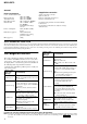
MDS-JE470 SERVICE MANUAL US Model Canadian Model AEP Model UK Model E Model Australian Model Ver 1.0 2001. 05 US and foreign patents licensed form Dolby Laboratories Licensing Corporation. Model Name Using Similar Mechanism MDS-S50 MD Mechanism Type MDM-7A Optical Pick-up Type KMS-260B/260E SPECIFICATIONS System MiniDisc digital audio system Disc MiniDisc Laser Semiconductor laser ( λ =780 nm) Emission duration: continuous Laser output MAX 44.
MDS-JE470 General Power requirements U.S.A. and Canadian models: 120 V AC, 60Hz European model: 230 V AC, 50/60Hz Australian model: 240 V AC, 50/60Hz Hong Kong model: 220 – 240 V AC, 50/60Hz Other models: 110 – 120/220 – 240 V AC, 50/60Hz Adjustable with voltage selector Power consumption 14 W (0.5 W in standby mode) Dimensions (approx.) 430 X 95 X285 mm (w/h/d) incl. projecting parts and controls Mass (approx.) 3.
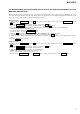
MDS-JE470 1. While pressing the lAMSL knob and x button, connect the power plug to the outlet, and release the lAMSL knob and x button. When the test mode is set, “[Check]” will be displayed. 2. Rotate the lAMSL knob and when “[Service]” is displayed, press the YES button. 3. Rotate the lAMSL knob and display “Err Display”. 4. Pressing the YES button sets the error history mode and displays “op rec tm”. 5. Select the contents to be displayed or executed using the lAMSL knob. 6.
MDS-JE470 Display History Mode for erasing the total spdl rp tm time These histories are based on the time of replacement of the spindle motor. If the spindle motor has been replaced, perform this procedure and erase the history. Procedure 1. Press the lAMSL knob when displayed as “spdl change” 2. Press the YES button when the display changes to “spdl change?” When “Complete!” is displayed, it means erasure has completed. spdl change Table of Error Codes Error Code TABLE OF CONTENTS Description 1.
MDS-JE470 SECTION 1 SERVICE NOTES SAFETY CHECK-OUT (US model only) After correcting the original service problem, perform the following safety checks before releasing the set to the customer: Check the antenna terminals, metal trim, “metallized” knobs, screws, and all other exposed metal parts for AC leakage. Check leakage as described below.
MDS-JE470 JIG FOR CHECKING BD BOARD WAVEFORM The special jig (J-2501-196-A) is useful for checking the waveform of the BD board. The names of terminals and the checking items to be performed are shown as follows.
MDS-JE470 Iop DATA RECORDING AND DISPLAY WHEN OPTICAL PICK-UP AND NON-VOLATILE MEMORY (IC195 OF BD BOARD) ARE REPLACED The Iop value labeled on the optical pick-up can be recorded in the non-volatile memory. By recording the value, it will eliminate the need to look at the value on the label of the optical pick-up. When replacing the optical pick-up or non-volatile memory (IC195 of BD board), record the Iop value on the optical pick-up according to the following procedure. Record Precedure: 1.
MDS-JE470 OPTICAL PICK-UP BLOCK TYPE DISCRIMINATION There are two types of the optical pick-up block in this model. These are compatible except for the laser power. Check the type of the optical pick-up block before replacement. Ajdust following items after replacing the optical pick-up block. • 5-6-2. Laser Power Check (See page 28) • 5-10.
MDS-JE470 CHECKS PRIOR TO PARTS REPLACEMENT AND ADJUSTMENTS Before performing repairs, perform the following checks to determine the faulty locations up to a certain extent. Details of the procedures are described in “5 Electrical Adjustments”. • 5-6-2. Laser power check (see page 28) • 5-6-3. Iop Compare (see page 28) • 5-6-4.
MDS-JE470 RETRY CAUSE DISPLAY MODE • In this test mode, the causes for retry of the unit during recording can be displayed on the fluorescent indicator tube. During playback, the “track mode” for obtaining track information will be set. This is useful for locating the faulty part of the unit. • The following will be displayed : During recording and stop : Retry cause, number of retries, and number of retry errors. During playback : Information such as type of disc played, part played, copyright.
MDS-JE470 Reading the Display: Convert the hexadecimal display into binary display. If more than two causes, they will be added. Example When 42 is displayed: Higher bit : 4 = 0100 t b6 Lower bit : 2 = 0010 t b1 In this case, the retry cause is combined of “CLV unlock” and “ader5”. When A2 is displayed: Higher bit : A = 1010 t b7+b5 Lower bit : 2 = 0010 t b2 The retry cause in this case is combined of “access fault”, “IVR rec error”, and “ader5”.
MDS-JE470 SECTION 2 GENERAL This section is extracted from instruction manual. Parts Identification The items are arranged in alphabetical order. Refer to the pages indicated in parentheses ( ) for details.
MDS-JE470 SECTION 3 DISASSEMBLY • This set can be disassembled in the order shown below. 3-1.
MDS-JE470 3-2. UPPER CASE (408226) 2 Case (408226) 1 Two screws (CASE 3TP2) 1 Screw (CASE 3TP2) 1 Two screws (CASE 3TP2) 3-3.
MDS-JE470 3-4. MAIN BOARD 6 Two screws (+BVTP3x8) 3 Connector (CN400) 2 Wire (flat type) (23core) (CN1) 1 Wire (flat type) (27core) (CN2) 7 MAIN board 4 Two screws (+BVTP3x8) 5 screw (+BVTP3x8) 3-5.
MDS-JE470 3-6. MECHANISM DECK SECTION (MDM-7A) 3 Mechanism deck 2 Two step screws (+BVTTWH M3) 2 Two step screws (+BVTTWH M3) 1 Harness 3-7. OVER LIGHT HEAD (HR901), BD BOARD Note 1: If you disconnect the connector (CN104), you can remove the BD board without removing the over write head (HR901). Note 2: Be careful to handle the over write head (HR901) because it is easy to be damaged. 2 Screw (P1.
MDS-JE470 3-8. HOLDER ASSY 2 Claw 3 6 Holder ASSY 5 4 Boss 4 Boss 1 Spring (holder), tension 3-9. LOADING MOTOR ASSY (M103) 1 Belt (loading) 2 Two screws (PWH1.7x2.
MDS-JE470 3-10. SLED MOTOR ASSY (M102), SLIDER 5 Remove the claw. Shift the slider in the arrow A direction. 3 4 Slider (EJ) A 6 Slider 8 Lever (head) 1 Two screws (BTP2X6) 2 Guide (L) 9 Two screws (PWH1.7X2.5) 7 Lever (CHG) 0 Motor ASSY, sled (M102) 3-11. OPTICAL PICK-UP qa Optical pick-up (KMS-260B/260E) 1 FLEXIBLE board 7 Main shaft 0 SL base 9 Screw (P1.7X6) 8 6 Two screws (K2X6) 4 Screw (BTP2X6) 5 Base (BU-A) 3 Gear (SD) 2 Screw (M1.
MDS-JE470 3-12. SPINDLE MOTER ASSY (M101) 2 Spindle motor ASSY (M101) 1 Three screws (M1.
MDS-JE470 SECTION 4 TEST MODE 4-1. PRECAUTIONS FOR USE OF TEST MODE • As loading related operations will be performed regardless of the test mode operations being performed, be sure to check that the disc is stopped before setting and removing it. Even if the A EJECT button is pressed while the disc is rotating during continuous playback, continuous recording, etc., the disc will not stop rotating. Therefore, it will be ejected while rotating.
MDS-JE470 4-5. SELECTING THE TEST MODE There are 26 types of test modes as shown below. The groups can be switched by rotating the l AMS L knob. After selecting the group to be used, press the YES button. After setting a certain group, rotating the l AMS L knob switches between these modes. Refer to “Group” in the table for details selected. All adjustments and checks during servicing can be performed in the test mode in the Service group. NOTE: Do not use the test mode in the [Develop] group.
MDS-JE470 4-5-1. Operating the Continuous Playback Mode 1. Entering the continuous playback mode 1 Set the disc in the unit. (Whichever recordable discs or discs for playback only are available.) 2 Rotate the l AMS L knob and display “CPLAY1 MODE”(C34). 3 Press the YES button to change the display to “CPLAY1 MID”. 4 When access completes, the display changes to “C = AD = ”. Note : The numbers “ ” displayed show you error rates and ADER. 2.
MDS-JE470 4-6. FUNCTIONS OF OTHER BUTTONS Function G Contents Sets continuous playback when pressed in the STOP state. When pressed during continuous playback, the tracking servo turns ON/OFF. x Stops continuous playback and continuous recording. M The sled moves to the outer circumference only when this is pressed. m The sled moves to the inner circumference only when this is pressed. REC MODE Switches between the pit and groove modes when pressed.
MDS-JE470 4-8. MEANINGS OF OTHER DISPLAYS Contents Display When Lit When Off G Servo ON Servo OFF X Tracking servo OFF Tracking servo ON REC Recording mode ON Recording mode OFF SYNC CLV low speed mode CLV normal mode L.SYNC ABCD adjustment completed OVER Tracking offset cancel ON B/1 Tracking auto gain OK A-/REP Focus auto gain OK REC MODE Pit Groove DISC/LP2 High reflection Low reflection SLEEP/SHUF CLV S CLV A MONO CLV LOCK CLV UNLOCK Tracking offset cancel OFF 4-9.
MDS-JE470 SECTION 5 ELECTRICAL ADJUSTMENTS Note : 260B: KMS-260B 260E: KMS-260E 5-1. PARTS REPLACEMENT AND ADJUSTMENT If malfunctions caused by Optical pick-up such as sound skipping are suspected, follow the following check. Check before replacement Start 5-6-2. Laser Power Check (See page 28) NG OK 5-6-3. Iop Compare (See page 28) NG OK 5-6-4. Auto Check (See page 29) NG Replace Optical pick-up or MDM-7A OK Other faults are suspected. Check the threading mechanism, etc.
MDS-JE470 Adjustment flow • Abbreviation OP: Optical pick-up Start Replace IC195 YES After turning off and then on the power, initialize the EEPROM For details, refer to 4-11. WHEN MEMORY NG IS DISPLAYED (See page 24) NO Replace OP or IO195 YES 5-7. INITIAL SETTING OF ADJUSTMENT VALUE (See page 31) YES 5-9. TEMPERATURE COMPENSATION OFFSET ADJUSTMENT (See page 31) NO Replace IC101, IC195, or D101 NO Replace OP, IC190, or IC195 YES 5-10.
MDS-JE470 5-2. PRECAUTIONS FOR CHECKING LASER DIODE EMISSION To check the emission of the laser diode during adjustments, never view directly from the top as this may lose your eye-sight. 5-3. PRECAUTIONS FOR USE OF OPTICAL PICKUP (KMS-260B/260E) As the laser diode in the optical pick-up is easily damaged by static electricity, solder the laser tap of the flexible board when using it. Before disconnecting the connector, desolder first. Before connecting the connector, be careful not to remove the solder.
MDS-JE470 5-5. USING THE CONTINUOUSLY RECORDED DISC * This disc is used in focus bias adjustment and error rate check. The following describes how to create a continuous recording disc. 1. Insert a disc (blank disc) commercially available. 2. Rotate the l AMS L knob and display “CREC1 MODE”. 3. Press the YES button again to display “CREC1 MID”. Display “CREC (0300)” and start to recording. 4. Complete recording within 5 minutes. 5. Press the MENU/NO button and stop recording . 6.
MDS-JE470 5-6-4. Auto Check This test mode performs C-REC and C-PLAY automatically for mainly checking the characteristics of the optical pick-up. To perform this test mode, the laser power must first be checked. Perform Auto Check after the laser power check and Iop compare. Procedure 1. Press the YES button. If “LDPWR minicheck” is displayed, it means that the laser power check has not been performed. In this case, perform the laser power check and Iop compare, and then repeat from step 1. 2.
MDS-JE470 16. Observe the waveform of the oscilloscope, and check that the specified value is satisfied. Do not rotate the l AMS L knob. (Traverse Waveform) A VC B Specified value : Below 10% offset value Offset value (%) = IA – BI X 100 2 (A + B) 17. Press the YES button and display “EF CD CHECK”. 18. Press the A EJECT button and remove the check disc (MD) TDYS-1. Note 1 : MO reading data will be erased during if a recorded disc is used in this adjustment.
MDS-JE470 5-7. INITIAL SETTING OF ADJUSTMENT VALUE 5-9. TEMPERATURE COMPENSATION OFFSET ADJUTMENT Note: Mode which sets the adjustment results recorded in the non-volatile memory to the initial setting value. However the results of the temperature compensation offset adjustment will not change to the initial setting value. If initial setting is performed, perform all adjustments again excluding the temperature compensation offset adjustment. For details of the initial setting, refer to “5-4.
MDS-JE470 7. Then, rotate the l AMS L knob and display “LDPWR CHECK”. 8. Press the YES button once and display “LD 0.9 mW $ ”. Check that the reading of the laser power meter become the specified value. 9. Press the YES button once more and display “LD 7.0 mW $ ”. Check that the reading the laser power meter and digital volt meter satisfy the specified value. Note down the digital voltmeter reading value. Specified Value : Laser power meter reading : LD 0.9mW : 0.85-0.91mW (260B) 0.90-0.96mW (260E) LD 7.
MDS-JE470 11. Rotate the l AMS L knob until the waveform of the oscilloscope moves closer to the specified value. In this adjustment, waveform varies at intervals of approx. 2%. Adjust the waveform so that the specified value is satisfied as much as possible. (Traverse Waveform) A VC B Specification A = B 12. Press the YES button, and save the adjustment results in the non-volatile memory. (“EFB = SAVE” will be displayed for a moment.) Next “EF MO ADJUS” is displayed.
MDS-JE470 5-14. ERROR RATE CHECK 5-14-1. CD Error Rate Check Checking Procedure : 1. Load a check disc (MD) TDYS-1. 2. Rotate the l AMS L knob and display “CPLAY1 MODE”. 3. Press the YES button twice and display “CPLAY1 MID”. 4. The display changes to “C = AD = ”. 5. Check that the C error rate is below 20. 6. Press the MENU/NO button, stop playback, press the A EJECT button, and remove the test disc. 5-14-2. MO Error Rate Check Checking Procedure : 1. Load a continuously recorded test disc (MDW-74/GA-1).
MDS-JE470 5-17. ADJUSTING POINTS AND CONNECTING POINTS [BD BOARD] (SIDE A) CN101 D101 [BD BOARD] (SIDE B) IC101 CN105 1 IC102 7 *NOTE IC151 IC190 IC195 23 1 27 CN103 1 CN102 NOTE:It is useful to use the jig. for checking the waveform. (Refer to Servicing Note on page 6.
MDS-JE470 SECTION 6 DIAGRAMS 6-1.
MDS-JE470 THIS NOTE IS COMMON FOR PRINTED WIRING BOARDS AND SCHEMATIC DIAGRAMS. (In addition to this, the necessary note is printed in each block.) • WAVEFORMS B C E Note: The components identified by mark 0 or dotted line with mark 0 are critical for safety. Replace only with part number specified. • • • • • • • • • Note: Les composants identifiés par une marque 0 sont critiques pour la sécurité. Ne les remplacer que par une piéce por tant le numéro spécifié. 1 IC101 ek (RF) These are omitted.
MDS-JE470 6-2.
MDS-JE470 – MAIN SECTION – A/D, D/A CONVERTER IC500 • SIGNAL PATH : PLAY (ANALOG OUT) : REC (ANALOG IN) J300 ADDT A 13 HIGH-PASS FILTER, DIGITAL ATTENUATOR SDTO (Page38) A/D CONVERTER BLOCK AINL SUBTRACKTION AINR AUDIO INTERFACE CONTROLLER DADT, BCK, LRCK B DADT 14 BCK (Page38) 12 LRCK SWDT, SCLK D 11 SWDT SCLK AOUTL– D/A CONVERTER BLOCK DIGITAL ATTENUATOR, SOFT MUTE SDTI BICK AOUTR+ AOUTR– LRCK CDTI 15 CCLK 16 CS 17 (Page38) AOUTL+ CLOCK GENERATOR, CLOCK DIVIDER CONTROL REG
MDS-JE470 6-3. PRINTED WIRING BOARD – BD Board – • See page 36 for Circuit Board Location. There are a few cases that the part isn’t mounted in model is printed on diagram. OPTICAL PICK - UP BLOCK (KMS - 260B/260E) BD BOARD BD BOARD (SIDE A) (SIDE B) 5 1 • Semiconductor Location Ref. No. Location D101 A-1 Q101 Q131 Q132 Q133 Q134 B-1 C-1 B-1 B-1 B-1 HR901 OVER WRITE HEAD 40 40 B A MAIN BOARD CN1 (Page 45) MAIN BOARD CN2 (Page 45) 4 2 3 • Semiconductor Location Ref. No.
MDS-JE470 6-4. SCHEMATIC DIAGRAM – BD SECTION (1/2) – • See page 37 for Waveforms. • See page 52 for IC Pin Functions. • See page 50 for IC Block Diagrams.
MDS-JE470 6-5. SCHEMATIC DIAGRAM – BD SECTION (2/2) – • See page 37 for Waveforms. • See page 53 for IC Pin Functions. • See page 50 for IC Block Diagrams.
MDS-JE470 6-6. SCHEMATIC DIAGRAM – MAIN SECTION (1/2) – • See page 37 for Waveforms. • See page 56 for IC Pin Functions. • See page 51 for IC Block Diagrams. 1 2 3 4 5 6 MAIN BOARD (2/2) 7 8 CN2 27P C680 JUMPER 9 12 13 D-GND 14 WRPWR REC-SW DIG-RST LDON SDA SENS MOD LIMIT-IN R61 10k SCL ADDT EEP-WP SWDT OUT-SW LRCK DADT DADT REG.
MDS-JE470 6-7. SCHEMATIC DIAGRAM – MAIN SECTION (2/2) – • See page 51 for IC Block Diagrams. IC440 M54641L LOADING DRIVER R441 22k R442 15k 1 Q440 UN4211-TA C442 0.01 Q440,445 REFERENCE 2 VOLTAGE SWITCH C441 100 16V 3 4 R443 22k Q445 2SA1175-HFE D433 1SS133T-72 5 D431 1SS133T-72 R431 100 R433 330 C432 22 25V R434 22k R432 680 C431 33 25V D432 1SS133T-72 D409 11EQS04 IC401 BA033T 6 D408 11EQS04 7 +3.
MDS-JE470 6-8. PRINTED WIRING BOARD – MAIN SECTION – • See page 36 for Circuit Board Location. There are a few cases that the part isn’t mounted in model is printed on diagram.
MDS-JE470 6-9. PRINTED WIRING BOARD – DISPLAY SECTION – • See page 36 for Circuit Board Location. There are a few cases that the part isn’t mounted in model is printed on diagram.
MDS-JE470 6-10. SCHEMATIC DIAGRAM – DISPLAY SECTION – S724 LEVEL/DISPLAY/CHAR R726 JW POWER LED S726 S723 REPEAT I/ POWER LED P.DOWN 3.3V SYS 3.3 KEY2 KEY2 AC GND GND AC 3.3V S722 CN701 15P CN710 4P CN720 4P R722 2.2k R723 3.3k R724 4.
MDS-JE470 6-11. PRINTED WIRING BOARD – POWER SECTION – • See page 36 for Circuit Board Location. There are a few cases that the part isn’t mounted in model is printed on diagram.
MDS-JE470 6-12. SCHEMATIC DIAGRAM – POWER SECTION – SP TR950 S990 VOLTAGE SELECTOR 115V C952 0.1 C951 0.1 230V TR900 POWER CN990 5P CN950 WIRE 5P TRANSFORMER CN921 11 SP JW903 JW902 JW904 JUMPER MAIN BOARD(2/2) CN400 JW901 5 EXCEPT C910 0.0022 AC RY910 RELAY 1 * NOT REPLACEABLE: D910 1SS133-72 BUILT IN TRANSFORMER C924 0.1 CN900 2P SP * (Page49) LF900 LINE FILTER C923 0.
MDS-JE470 6-13.
MDS-JE470 IC500 AK4524 (MAIN BOARD) VCOM 1 AINR 2 AOUTR+ AOUTR– AOUTL+ AOUTL– AINL 3 28 27 26 25 VREF AGND 4 5 6 7 24 DGND 23 VD 22 VT D/A CONVERTER BLOCK A/D CONVERTER BLOCK VA TEST XTO 8 XTI 9 XTALE 10 LRCK BICK SDTO SDTI 11 12 13 14 CLOCK GENERATOR & DIVIDER 21 CLKO 20 M/S 19 PD H.P.F. D-ATT AUDIO INTERFACE CONTROLLER 18 17 16 15 CONTROL REGISTER INTERFACE D-ATT, S-MUTE CIF CS CCLK CDTI IC440 M54641L (MAIN BOARD) VCC 1 OUT2 2 REG 8 VCC IN1 3 INPUT AMP. CONTROL POWER AMP.
MDS-JE470 6-14. IC PIN FUNCTION DESCRIPTION • IC101 CXA2523AR RF Amplifier (BD BOARD) Pin No. Pin Name I-V converted RF signal I input J I I-V converted RF signal J input VC O Middle point voltage (+1.
MDS-JE470 • IC151 CXD2662R Digital Signal Processor, Digital Servo Signal Processor (BD BOARD) Pin No.
MDS-JE470 Pin No.
MDS-JE470 Pin No. Pin Name 86 TFDR 87 I/O Description O Tracking servo drive PWM output (+) DVDD I +3V power supply (Digital) 88 FFDR O Focus servo drive PWM output (+) 89 FRDR O Focus servo drive PWM output (–) 90 FS4 O 176.
MDS-JE470 • IC1 M30803MG-107FP SYSTEM CONTROL (MAIN BOARD) Pin No. I/O Description 1 FLDT O Serial data signal output to the display driver. 2 FLCK O Serial clock signal output to the display driver. L: Active 3 A1-IN I A1 Control input. (Fixed at L) I Remote control input. 4 5-7 56 Pin Name SIRCS NC — I Not used. 8 BYTE 9 CNVSS 10 XIN-T I Not used . (open) 11 XOUT-T O Not used . (open) 12 S.RST I System rest input. L : ON 13 XOUT O Main clock output.
MDS-JE470 Pin No. Pin Name I/O Description 40 ADA. LATCH O 41 EPN I 42 L : DINT1/H : CLIP — Not used. (open) 43 NC — Not used. 44 PROTECT I Recording-protection claw detection input from the protection detection switch. H: Protect 45 SCL O Clock signal output to the EEP-ROM. 46 CE O Not used. 47 EEP-WP O EEP-ROM write protect signal output.
MDS-JE470 Pin No. 81 Pin Name I/O Description STB O Strobe signal output to the power supply circuit. H: Power supply ON: L: standby 82 BEEP SW — Not used. 83 REC — Not used. 84 FLCS O Chip select signal output to the MSM9202 (IC760) 85, 86 D.VOL0,1 — Not used. 87, 88 JOG0, JOG1 I Jog dial pulse input from the rotary encoder. 89 IOP I Optical Pick-up voltage (current) detect signal input. 90 DISTINATION I Model discrimination. 91 MODEL SEL I Model discrimination.
MDS-JE470 SECTION 7 EXPLODED VIEWS NOTE: • -XX, -X mean standardized parts, so they may have some differences from the original one. • Items marked “*” are not stocked since they are seldom required for routine service. Some delay should be anticipated when ordering these items. • The mechanical parts with no reference number in the exploded views are not supplied. • Hardware (# mark) list and accessories and packing materials are given in the last of this parts list. 7-1.
MDS-JE470 7-2. FRONT PANEL SECTION 54 59 54 63 54 54 FL750 54 54 56 54 61 62 not supplied 60 57 51 64 Ref. No. 51 Part No. Description 65 Remarks 51 51 54 56 X-4953-710-1 PANEL ASSY, FRONT...(BLACK) (AEP,UK,HK,SP,AUS) X-4953-711-1 PANEL ASSY, FRONT...(SILVER) (AEP,UK) X-4953-712-1 PANEL ASSY, FRONT...(BLACK) (US,CND) 4-951-620-01 SCREW (2.6X8), +BVTP 4-228-630-01 SPRING (LID), TENSION COIL 57 57 59 60 4-228-629-81 4-230-848-21 1-681-737-12 A-2007-907-A 60 LID (MD)...
MDS-JE470 7-3. MECHANISM SECTION-1 (MDM-7A) 312 313 311 314 310 319 315 309 316 #2 305 317 304 305 308 303 318 306 302 307 320 302 301 Ref. No. Part No. Description Remarks Ref. No. Part No. Description * 301 302 303 304 305 4-996-267-01 4-231-319-01 4-227-007-01 4-227-025-01 3-372-761-01 BASE (BU-D) SCREW (2X6) CZN, +B (P) TRI GEAR (SB) BELT (LOADING) SCREW (M1.
MDS-JE470 7-4. MECHANISM SECTION-2 (MDM-7A) HR901 359 358 360 #3 356 364 357 355 367 362 #3 359 362 354 353 368 353 352 352 S102 M101 365 363 366 M102 361 351 not supplied 353 353 M103 352 The components identified by mark 0 or dotted line with mark 0 are critical for safety. Replace only with part number specified. Ref. No. Part No.
Ref. No. Part No. SECTION 8 ELECTRICAL PARTS LIST Description Remarks NOTE: • Due to standardization, replacements in the parts list may be different from the parts specified in the diagrams or the components used on the set. • -XX, -X mean standardized parts, so they may have some difference from the original one. • Items marked “*” are not stocked since they are seldom required for routine service. Some delay should be anticipated when ordering these items.
MDS-JE470 BD Ref. No. IC190 IC195 Part No. Description Remarks Part No. Description R116 R117 R118 R119 R120 1-216-839-11 1-216-837-11 1-218-855-11 1-218-863-11 1-218-889-11 METAL CHIP METAL CHIP METAL CHIP METAL CHIP METAL CHIP 33K 22K 2.2K 4.7K 56K 5% 5% 0.5% 0.5% 0.5% 1/16W 1/16W 1/16W 1/16W 1/16W R121 R122 R123 R124 R125 1-218-863-11 1-218-855-11 1-216-819-11 1-216-809-11 1-216-815-11 METAL CHIP METAL CHIP METAL CHIP METAL CHIP METAL CHIP 4.7K 2.2K 680 100 330 0.5% 0.
DISPLAY Ref. No. Part No. Remarks Ref. No. A-2007-907-A DISPLAY BOARD, COMPLETE (US,CND) A-2007-911-A DISPLAY BOARD, COMPLETE (AEP,UK,HK,AUS) A-2007-915-A DISPLAY BOARD, COMPLETE (SP) Description R781 R782 Part No. CERAMIC ELECT ELECT CERAMIC CERAMIC 0.1uF 10uF 10uF 0.001uF 0.001uF C763 C760 C764 C765 C766 1-162-294-31 1-164-159-11 1-164-159-11 1-126-153-11 1-164-159-11 CERAMIC CERAMIC CERAMIC ELECT CERAMIC 0.001uF 0.1uF 0.1uF 22uF 0.
MDS-JE470 MAIN Ref. No. Part No. Description Remarks C62 1-164-159-11 CERAMIC 0.1uF C87 C88 C89 C100 C111 1-162-306-11 1-162-306-11 1-162-294-31 1-126-964-11 1-162-290-31 CERAMIC CERAMIC CERAMIC ELECT CERAMIC 0.01uF 0.01uF 0.001uF 10uF 470PF C112 C113 C161 C165 C166 1-128-551-11 1-128-551-11 1-137-505-11 1-137-503-11 1-137-503-11 ELECT ELECT MYLAR MYLAR MYLAR C171 C172 C176 C177 C211 1-137-368-11 1-130-471-00 1-128-551-11 1-162-290-31 1-162-290-31 C212 C213 C261 C265 C266 Ref. No. Part No.
MDS-JE470 MAIN Ref. No. Part No.
MDS-JE470 MAIN PT VOL-SEL Ref. No. Part No. Description R513 R514 R515 R516 1-249-401-11 1-249-401-11 1-247-807-31 1-247-807-31 CARBON CARBON CARBON CARBON 47 47 100 100 5% 5% 5% 5% Remarks 1/4W F 1/4W F 1/4W 1/4W R517 R551 R552 R554 R556 1-247-807-31 1-247-903-00 1-249-411-11 1-249-411-11 1-249-411-11 CARBON CARBON CARBON CARBON CARBON 100 1M 330 330 330 5% 5% 5% 5% 5% 1/4W 1/4W 1/4W 1/4W 1/4W Ref. No. Part No.
MDS-JE470 69
MDS-JE470 REVISION HISTORY Clicking the version allows you to jump to the revised page. Also, clicking the version at the upper right on the revised page allows you to jump to the next revised page. Ver. Date 1.0 2001.