MDX-61 SERVICE MANUAL US Model Canadian Model AEP Model UK Model E Model Ver 1.1 2001.08 This set is automatic electrical adjustment. Model Name Using Similar Mechanism MDX-60 Base Mechanism Type MG-798-133 Optical Pick-Up Name KMS-193C/J2N SPECIFICATIONS System Mini disc digital audio system Laser Diode Properties Material: GaAlAs Wavelength: 780nm Emission Duration: Continuous Laser out-put Power: Less than 44.
TABLE OF CONTENTS 1. GENERAL ..................................................................... 3 2. DISASSEMBLY ............................................................ 7 3. DIAGRAMS 3-1. 3-2. 3-3. 3-4. 3-5. 3-6. 3-7. 3-8. Block Diagram ................................................................... Printed Wiring Boards - Servo Section – ........................... Schematic Diagram – Servo Section – .............................. Schematic Diagram – Main Section – ......................
SECTION 1 GENERAL –3– This section is extracted from instruction manual.
–4–
–5–
–6–
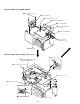
SECTION 2 DISASSEMBLY Note: Follow the disassembly procedure in the numerical order given. FRONT PANEL ASS’Y, CASE (UPPER) 5 case (upper) 1 two screws (B2.6 × 6) 1 two screws (B2.6 × 6) 2 claw 3 front panel ass’y 2 claw 4 connector (CN620) 1 two screws (B2.
CHASSIS (GEAR) ASS’Y, MAIN BOARD 1 three screws (P1.7 × 1.8) 2 chassis (gear) ass’y 3 special flat screw (1.7 × 3) 4 flexible board (CN500) 5 connector (CN602) 3 two special flat screws (1.7 × 3) 6 flexible board (CN610) 7 three connectors (CN603, 700, 701) 8 MAIN board CHASSIS (BASE) ASS’Y, CHASSIS (OP) ASS’Y 3 worm wheel (LD) 5 Pull up the chassis (OP) ass’y in the arrow A direction. 1 four screws (P1.7 × 1.8) A 1 screw (P1.7 × 1.8) 1 screw (P1.7 × 1.
SERVO BOARD 2 three special head screws (M1.7 × 2) 3 flexible board (CN100) 5 connector (CN301) 6 servo board 1 flexible board (CN200) 4 flexible board (CN400) OPTICAL PICK-UP (KMS-193C/J2N) 1 two screw (K1.7 × 3.
SECTION 3 DIAGRAMS • Circuit Boards Location SW board POWER board MAIN board LAMP board – 10 – SERVO board
MDX-61 BLOCK DIAGRAM OPTICAL PICK-UP BLOCK (KMS-193C/J2N) F C B D A J E 12 7 F XRST 17 XRST XRST 59 MD-RST 2 4 C SWDT 18 SWDT XLAT 58 MD-LAT 10 3 B SCLK 19 SCLK SWDT 45 MD-SO XLAT 20 XLAT SCLK 51 MD-CKO 48 J RFO 44 8 2 A AGCI 43 4 5 D RF 41 58 RFI XLAT 10 XLAT 6 E TE 26 77 TE SCLK 9 SCLK 3 47 I SE 29 76 SE SWDT 8 SWDT ADFG 33 82 ADFG XRST 16 XRST AUX 34 68 AUX1 SENS 12 SENS 67 FE SRDT 11 SRDT BOTM 38 65 BOTM SQSY 14 SQSY PEAK 39 64 PEAK FOK
• IC Block Diagrams – MAIN section – – SERVO section – CXD2535CR-1 DICV 25 D4 49 DIPO XWE 3 24 D3 48 TEST2 XRAS 4 47 MVC1 NC 5 46 RAOF NC 6 EFM MODULATOR 45 EFMO REGISTER EFM DEMODULATOR SERVO DSP TRDR 85 TRACKING PWM TRACKING SERVO TFDR 86 FOCUS PWM FOCUS SERVO FFDR 87 SLED PWM SLED SERVO A2 11 EFM SYNC DETECTOR/ PROTECTOR 43 GFS 42 GTOP 41 WFCK A3 12 TIMING GENERATOR 39 WDCK (4) INPUT BUFFER 14 A4 CS4330-KSR-H 36 MCLK 35 XTAI 34 XTAO 32 BCK SERIAL INPUT INTERFACE DEM
3-8. IC PIN FUNCTION DESCRIPTION SERVO BOARD IC100 CXA1981AR (RF AMP) Pin No.
SERVO BOARD IC200 CDX2535CR-1 (DIGITAL SIGNAL PROCESSOR, DIGITAL SERVO SIGNAL PROCESSOR, EFM/ACIRC ENCODER/DECODER) Pin No. Pin Name I/O Function 1 FS256 O 11.
Pin No. Pin Name I/O 41 WFCK O 42 GTOP O 43 GFS O Function WFCK clock (7.35kHz) signal output (When playback : EFM decoder PLL system, When recoding : EFM encoder PLL system) Not used this set (OPEN) Opens the playback EFM frame sync protection window when “H” Not used this set (OPEN) The playback EFM frame sync and interpolation protection timing match when “H” Not used this set (OPEN) 44 XPLCK O EFM decoder PLL clock (98Fs=4.
Pin No. Pin Name I/O Function 79 DCHG I (A) 80 APC I (A) Input terminal for the laser APC 81 TEST1 I Test input terminal (Fixed at “L”) 82 ADFG I Connected to the Ground Not used this set (Fixed at “L”) ADIP double turned FM signal input from CXA1981AR (IC100) (22.
MAIN BOARD IC500 CXD2536R (SHOCK PROOF MEMORY CONTROLLER, ATRAC ENCODER/DECODER) Pin No.
Pin No. Pin Name I/O Function 50 VSS – Ground terminal 51 VDD – Power supply terminal (+3.
MAIN BOARD IC600 CXP84340-043Q (SYSTEM CONTROLLER) Pin No.
Pin No.
SECTION 4 EXPLODED VIEWS NOTE: • -XX and -X mean standardized parts, so they may have some difference from the original one. • Color Indication of Appearrance Parts Example: KNOB, BALANCE (WHITE) . . . (RED) ↑ ↑ Parts Color Cabinet's Color 4-1. • Items marked “*” are not stocked since they are seldom required for routine service. Some delay should be anticipated when ordering these items. • The mechanical parts with no reference number in the exploded views are not supplied.
Ver 1.1 4-2. MECHANISM SECTION-1 (MG-798-133) 59 58 71 57 69 60 56 55 #2 54 #4 60 S902 #4 S903 62 M903 61 70 53 52 52 60 #2 #3 67 51 64 #2 63 #2 M904 68 65 #2 #2 66 52 Ref. No. Part No. Description WHEEL (ELV), WORM WASHER, POLYETHYLENE SCREW (1.
4-3. MECHANISM SECTION-2 (MG-798-133) 129 127 128 #2 #2 127 129 112 129 128 #2 110 111 112 (US, Canadian) 114 130 131 132 115 116 113 not supplied 130 101 126 109 108 107 106 105 104 117 118 124 119 126 102 120 125 103 121 122 101 123 125 Ref. No. Part No.
4-4. MECHANISM SECTION-3 (MG-798-133) #6 #6 #6 158 159 157 160 156 155 155 157 156 155 161 174 163 162 RV901 #6 M901 #2 #4 M902 165 164 154 S901 167 153 166 #6 168 #7 152 #5 171 #2 151 170 169 #5 172 173 The components identified by mark ! or dotted line with mark ! are critical for safety. Replace only with part number specified. Ref. No. Les composants identifiés par une marque ! sont critiques pour la sécurité.
EHS FLEXIBLE SECTION 5 ELECTRICAL PARTS LIST NOTE: • Due to standardization, replacements in the parts list may be different from the parts specified in the diagrams or the components used on the set. • -XX and -X mean standardized parts, so they may have some difference from the original one. • RESISTORS All resistors are in ohms. METAL: Metal-film resistor. METAL OXIDE: Metal oxide-film resistor. F: nonflammable • Items marked “*” are not stocked since they are seldom required for routine service.
MAIN Ref. No. Part No. Description Remark * CN604 CN700 CN701 1-580-056-21 PIN, CONNECTOR 3P 1-580-055-21 PIN, CONNECTOR 2P 1-580-055-21 PIN, CONNECTOR 2P 8-719-421-36 8-719-988-62 8-719-988-62 8-719-988-62 8-719-422-64 5% 1/16W R505 R506 R520 R521 R550 1-218-733-11 1-218-730-11 1-216-811-11 1-218-664-11 1-216-797-11 METAL CHIP METAL CHIP METAL CHIP METAL CHIP METAL CHIP 51K 39K 150 68 10 0.50% 0.50% 5% 0.
MAIN Ref. No. Part No. Description Remark RB604 1-239-516-11 RESISTOR, NETWORK (1608) 1Kx4 RB605 RB606 RB607 RB609 1-239-517-11 1-239-516-11 1-239-516-11 1-239-516-11 RESISTOR, NETWORK (1608) 100Kx4 RESISTOR, NETWORK (1608) 1Kx4 RESISTOR, NETWORK (1608) 1Kx4 RESISTOR, NETWORK (1608) 1Kx4 < SWITCH > S600 1-571-914-21 SWITCH, KEY BOARD (STOP) < THERMISTOR > TH600 1-810-421-11 THERMISTOR NTH5G36B103K01TE 10K < VIBRATOR > X500 1-760-168-11 VIBRATOR, CRYSTAL (45.
Ver 1.1 POWER Ref. No. SENSOR Part No. Description Remark < COIL > L950 L951 L952 L953 L954 1-409-640-21 1-403-584-11 1-409-640-21 1-403-584-11 1-409-640-21 COIL, CHIP CHOKE COIL, CHIP CHOKE COIL, CHIP CHOKE COIL, CHIP CHOKE COIL, CHIP CHOKE 10uH 33uH 10uH 33uH 10uH Ref. No. Part No.
SERVO Ref. No. Part No. Description Remark * A-3222-980-A SERVO BOARD, COMPLETE ********************* C102 C103 C104 C105 C106 1-135-259-11 1-135-259-11 1-162-964-11 1-162-969-11 1-164-227-11 TANTAL. CHIP TANTAL. CHIP CERAMIC CHIP CERAMIC CHIP CERAMIC CHIP 10uF 20% 10uF 20% 0.001uF 10% 0.0068uF 10% 0.022uF 10% 6.3V 6.3V 50V 25V 25V C107 C108 C111 C113 C114 1-162-970-11 1-162-970-11 1-104-852-11 1-107-826-11 1-162-970-11 CERAMIC CHIP CERAMIC CHIP TANTAL. CHIP CERAMIC CHIP CERAMIC CHIP 0.01uF 0.
MDX-61 SERVO Ref. No. RB203 Part No. Description Remark Ref. No. Part No.
MDX-61 MEMO – 51 –
MDX-61 REVISION HISTORY Clicking the version allows you to jump to the revised page. Also, clicking the version at the upper right on the revised page allows you to jump to the next revised page. Ver. 1.1 1.0 Date 2001.08 1998.01 1997.01 Description of Revision Correction-1 is included.