3-277-722-11 (1) Video Communication System Operating Instructions (Version 2.0) Before operating the unit, please read this manual thoroughly and retain it for future reference.
English Owner’s Record The model and the serial numbers are located at the rear. Record the serial number in the space provided below. Refer to these numbers whenever you call upon your Sony dealer regarding this product. Model No. PCS-TL33 Serial No. WARNING To reduce a risk of fire or electric shock, do not expose this product to rain or moisture. To avoid electrical shock, do not open the cabinet. Refer servicing to qualified personnel only.
Table of Contents Precautions ......................................................................................8 Chapter 1 Installation and Preparation Using This Manual ........................................................................... 9 Features.......................................................................................... 10 System Components ..................................................................... 11 Basic System Components .........................................
Device Setup Menu ............................................................................. 25 Audio Setup Menu............................................................................... 27 Network Setup Menu........................................................................... 27 Communication Mode Menu............................................................... 29 Administrator Setup Menu .................................................................. 32 Display Setup Menu .............
Adjusting the Picture Quality .............................................................. 57 Adjusting the Volume ......................................................................... 57 Cutting Off the Sound Momentarily - Mic Off Function.................... 57 Cutting Off the Sound On Answering - Mic Off Function ................. 57 Synchronizing Audio and Video - Lip Sync Function ........................ 57 Reducing Echo - Echo Canceller.........................................................
Chapter 5 Data Conference Using Data Solution Module Installing the Data Solution Module............................................. 72 Connection Example Using the Data Solution Module .............. 73 Using Video From Connected Equipment for a Conference ..... 74 Operating the System During a Conference........................................ 74 Chapter 6 Encrypted Videoconference via LAN Preparing for an Encrypted Videoconference via LAN ..............
Receiving a Call While PC Screen Is Shown...................................... 89 Adjusting the Picture Quality on the Display .............................. 89 Display Setup Menu for Videoconference .......................................... 89 Display Setup Menu for the Computer Picture ................................... 90 Differences in Wide Mode Settings .................................................... 91 Chapter 9 Web Control Function Open the Web Page ..........................................
Precautions Operating or storage location Avoid operating or storing the system in the following locations: • Extremely hot or cold places • Humid or dusty places • Places exposed to strong vibration • Close to sources of strong magnetism • Close to sources of powerful electromagnetic radiation, such as radios or TV transmitters • Noisy places LCD screen Notes on use • Do not expose the LCD screen surface to the sun. Doing so may damage the screen surface.
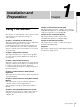
Chapter 1 Using This Manual Chapter 7: Videoconference Using SIP This chapter guides you how to conduct a videoconference using SIP with an IP phone, etc. Installing the optional SIP software is required for a session using SIP. The chapters cover the following contents; please read the chapters that may be required for your type of videoconference. Chapter 8: Use as Computer Display This chapter shows you how to use the Video Communication System as a computer display.
Features Chapter 1 Installation and Preparation The PCS-TL33 Video Communication System is a videoconferencing system that allows natural, face-to-face communications with a remote party by transmitting and receiving images and sound via a LAN (Local Area Network).
Automatic and manual image capturing System Components The PCS-TL33 Video Communication System is composed of basic system components for a basic videoconference, and optional equipment for an enhanced videoconference. KIOSK Mode available Basic System Components You can simplify operations and make calling with One Touch Dial the only available operation. The PCS-TL33 Video Communication System is the basic system of the Videoconferencing System.
Optional Equipment The following optional devices are used to enhance your videoconference. Chapter 1 Installation and Preparation Unit Description Data Solution Module PCSADSM1 Serves for transmitting the display image of a connected computer and also allows connection of a projector for displaying the computer image.
i Online lamp Shows mainly the incoming/outgoing call status. Chapter 1 Installation and Preparation j (Mic Off) button and indicator Lets you suppress the sound from the local system. Press the button again to resume sending the sound to the remote system. a Rear cover Removing this cover gives access to the connector panel. The connecting section between the stand and the display is also located behind the panel. You can adjust the height of the display by changing the screw positions.
e PC port This connector is used when the same mouse is to be used for the PCS-TL33 and for a computer connected to the RGB IN connector. Link the connector to a USB port on the computer. Indicator Status 100/ Lit orange 10 Mbps Out Meaning 100 Mbps 10 Mbps * The indicator is lit while the system is starting up. If abnormal temperature is detected, the indicator flashes and power turns off. Chapter 1 Installation and Preparation Note Use a USB cable that is 3 m (10 ft.) or shorter.
To attach the rear cover System Connections Push the cover in while aligning the four stubs. This section describes the typical system connections. Chapter 1 Installation and Preparation About the Connectors The connectors of the system are located under the rear cover. Remove the cover to make connections, and then replace the cover again. To remove the rear cover Pull the rear cover toward you. Connection Precautions Warning • Use only the supplied AC adapter and power cord.
3 Tighten the 4 screws using a coin or a similar object to secure the stand. 4 Attach the rear cover again. Adjusting the Height of the Display Chapter 1 Installation and Preparation The stand and the display section of the PCS-TL33 are joined by fastening screws. There are three sets of screw holes, spaced 25 mm apart. In the factory default condition, the display is fixed in the lowest position. By choosing a different set of screw holes, you can change the height of the display.
Turning the System On/ Off Chapter 1 Installation and Preparation This section describes how to turn the Video Communication System on and off. Before turning the system on, make sure that system connections have been completed correctly. The indicator of the switch lights up in orange and power to the Video Communication System comes on. When powering on is complete, the indicator lights up in green. The launcher menu appears on the display and the picture of the local camera is also shown.
accidental problem such as a power interruption during upgrading. If the Data Solution Module or other equipment is not recognized properly after power is restored, consult a Sony dealer. Chapter 1 Installation and Preparation Turning the System Off 1 Press the (Power) switch twice. After pressing the switch once, the message “To enter standby mode, wait for a few moments. To turn off the power, press the power switch again.” appears. Press the power switch again.
Setting Up the System for the First Time — Initial Setup Wizard 2/2 DHCP Mode IP Address Network Mask Gateway Address DNS Address Back DHCP Mode: Sets the DHCP (Dynamic Host Configuration Protocol). Auto: Automatically assigns your IP address, subnet mask, gateway address and DNS address. Off: Deactivates DHCP. In this case you must set your IP address, subnet mask, gateway address and DNS address manually. Host Name: Enter your host name. IP Address: Enter your IP address.
Using the Menu Chapter 1 Installation and Preparation The Video Communication System uses the on-screen menus to make various adjustments and settings. This section gives a brief introduction of the menus. Menu Configurations The menus of this system configure as described below. For more detailed menu configurations, refer to “Menu Configuration” on page 123.
Menu Icons Phone Book menu Selecting an icon shown on the screen displays the respective menu. Icon Displayed menu ALL Phone Book A-I AUTO J-S Takanawa 0657896709 T-Z HQ5Room6 sip: sony@abcd.com 0-9 Private Phone Book menu New HQ5Room6 sip: sony@abcd.com History menu HQ5Room6 sip: sony@abcd.com Camera Control menu HQ5Room6 sip: sony@abcd.com EMPTY Status & Info menu HQ5Room6 sip: sony@abcd.com Still Image menu Right-click the mouse to display a help message.
History menu The menu appears when you click “Camera Control” on the menu selection screen. 1/3 History ALL OUT IN 2005.07.30 10:10 05032105678 OUT 2005.07.30 10:10 0657896709 OUT 2005.07.30 10:10 sip: sony@abcd.com IN 2005.07.30 10:10 sip: sony@abcd.com OUT 2005.07.30 10:10 sip: sony@abcd.com IN 2005.07.30 10:10 sip: sony@abcd.com IN 2005.07.30 10:10 sip: sony@abcd.com For details on the Camera Control menu, see pages 58 60.
Image Viewer menu Dial Number 1/3 Image viewer A/a B C D E F G H I 1 2 3 J K l M N O P Q R 4 5 6 S T U V W X Y Z " 7 8 9 # @ _ & : ; - / . 0 , ^ ( ) ! ? + = / % < > ~ Backspace OK Load Send Delete all Space Cancel Delete Close Format $ IP:012.345.678.912 Right-click the mouse to display a help message. In situations where alphanumeric text input is required, for example when a text field in a menu is selected, a soft keyboard appears.
Registration and Setup Chapter 2 Chapter 2 Registration and Setup Submenus available from the Setup menu Selecting the respective item brings up the following menus. This chapter describes the general registration and settings procedures.
To page up or down the selected menu When a menu has several pages, a scroll bar will appear at the right side of the screen. To advance to the next page, click the Page button at the bottom of the scroll bar. To go back to the previous page, click the Page button at the top of the scroll bar. You can also drag the scroll bar up and down using the mouse to scroll through the pages. Device Setup Menu Page 1/2 Note Some items cannot be set while a communication session is in progress.
Thai: The display language is set to Thai. Traditional Chinese: The display language is set to Traditional Chinese. Chapter 2 Registration and Setup Number Display Select the information to display as identification for your system in the launcher menu, such as IP or SIP information. IP: Displays your IP address. SIP: User Name: Displays the SIP user name registered with the SIP server when conducting a videoconference using SIP.
Audio Setup Menu The Audio Setup menu is used to set various audio items. Call Volume Use this item to set the speaker/headphone volume for videoconferences. Page 1/1 Network Setup Menu The level meter indicating the audio input level is displayed. Lets you make LAN and SIP related settings.
Network Mask Enter the subnet mask. The display shows usable port numbers. For details on the port numbers used, see “List of Port Numbers Used on the PCS-TL33” on page 119. Gateway Address Enter the default gateway address. DNS Address Enter the DNS (Domain Name System) address.
SIP Page 3/3 UDP: Use UDP (User Datagram Protocol). Port Number Input the port for the SIP server. LAN 3/3 SIP Fourth SIP Domain Enter the SIP domain name. Up to 17 alphanumeric characters can be entered. SIP Proxy Server Address Proxy Port 5060 Registrar Server Address Registrar Port 5060 Registered User Name Enter the user name registered on the SIP server. Up to 17 alphanumeric characters can be entered. OK Cancel IP:012.345.678.912 Right-click the mouse to display a help message.
Video Frame Select the send video frame rate. Auto: The frame rate adjusts automatically. 15fps: Send CIF format video at a maximum rate of 15 frames per second. 30fps: Send CIF format video at a maximum rate of 30 frames per second. Note Chapter 2 Registration and Setup If the video frame rate is set to 30fps when the camera frame rate is set to 15fps or Auto, the actual frame rate of the picture may be 15fps, depending on the usage environment. Audio Mode Select an audio compression method.
Note Page 3/3 “SIP: No-Video” is only enabled when the optional PCSASP1 SIP software is installed. Encryption via LAN Video Frame Select the receive video frame rate. Auto: The frame rate adjusts automatically. 15fps: Receive CIF format video at a maximum rate of 15 frames per second. 30fps: Receive CIF format video at a maximum rate of 30 frames per second. Note If the far-end videoconferencing system does not support the audio compression method selected at the PCS-TL33, the G.
Administrator Setup Menu The Administrator Setup menu is used for the system administrators. When you specify an administrator password in this menu, that password will be required when making changes in the setup menus (excluding the Display Setup menu) and Phone Book. Entering the password is also required to access the Administrator Setup menu. Chapter 2 Registration and Setup Page 1/11 Save Phone Book Saves the data in the Phone Book in a “Memory Stick”.
User Alias Enter the user name (H.323 alias) to be registered in the gatekeeper. Page 4/11 4/11 Administrator Setup User Number Enter the user number (E.164 number) to be registered in the gatekeeper. Packet Resend Request Adaptive Rate Control On Off On Off Auto Negotiation LAN Mode Page 3/11 SNMP Mode On OK Off Cancel Trap Destination Right-click the mouse to display a help message. public Community IP:012.345.678.
Page 5-8/11 5/11 Administrator Setup TOS(Video) Off Minimum Cost Selects whether or not to specify the bit rate of Minimum Cost for the TOS field. On: Specifies the bit rate of Minimum Cost for the TOS field. Off: Does not specify the bit rate of Minimum Cost for the TOS field. IP Precedence Low Delay On Off High Throughput On Off High Reliability On Off Minimum Cost On Off Diffserve Chapter 2 Registration and Setup OK Cancel Right-click the mouse to display a help message. IP:012.345.
Off: Does not use the static IP for a PPPoE connection. Fixed IP Address for PPPoE Enter the static IP address when “Fixed IP for PPPoE” is set to “On”. Save Application Software Saves application software to a “Memory Stick”. Update software Performs a software update or rollback using a “Memory Stick.” Note Primary DNS Enter a primary DNS address. When performing a rollback, you can revert as far back as the factory-installed version. Secondary DNS Enter a secondary DNS address.
Chapter 2 Registration and Setup Shared Phone Book Allows you to select whether to use the Shared Phone Book located on the server. On: Enables use of the Shared Phone Book. Off: Disables use of the Shared Phone Book. Quality Mode Selects the color tone of the image. Vivid: Slightly bluish color tone. Standard: Setting between Vivid and Pro. Pro: Slightly reddish color tone. SPB Mode Selects whether to use the server managing the Shared Phone Book.
Brightness Adjusts the picture brightness. The brightness increases as the value gets larger. Backlight Adjusts the brightness of the backlight. The backlight gets brighter as the value gets larger. Reset Resets the settings to the default condition. Reset Resets the settings to the default condition. Screen Resolution/Refresh Rate Displays the screen resolution and refresh rate. Note The adjustment range of the H Shift and V Shift may differ depending on the specifications of the RGB signal input.
Registering a Remote Party in the Phone Book Chapter 2 Registration and Setup You can register the IP address and other information for a remote party in the Phone Book, allowing you to dial the party very easily. Up to 500 remote parties can be registered in the Phone Book. You can also store a still image such as a participant’s portrait in the index list. In addition to the regular Phone Book of the Video Communication System, you can create a Private Phone Book on a “Memory Stick”.
3 ALL J-S T-Z The selected party is deleted. List Edit Index A-I Click “OK”. To cancel deleting Click “Cancel” in step 3. Address Line I/F LAN Bandwidth IP 1024 0-9 Video Mode New Video Frame 15fps Audio Mode Auto Auto Note Far End Camera Control On Off H.239(Presentation) On Off Back Duplicate Save Cancel IP:012.345.678.912 Changing the Contents of the Phone Book You can change the IP address, name, or other setting registered in the Phone Book. 1 Open the Phone Book menu.
registered in the Phone Book are copied to the inserted “Memory Stick”. To delete the Private Phone Book from the “Memory Stick” Chapter 2 Registration and Setup 2 Open Page 1 of the Administrator Setup menu.
Using the Shared Phone Book Using the Shared Phone Book function, a phone book located on a server can be accessed by multiple Sony Video Communication System units. For details about settings, consult your network administrator. To display the Shared Phone Book Click at the bottom left of the Phone Book screen to switch the display to the Shared Phone Book. ALL Phone Book A--I AUTO J--S T--Z 0--9 New Note Takanawa 0657896709 HQ5Room6 sip: sony@abcd.com HQ5Room6 sip: sony@abcd.
Checking the History of Outgoing and Incoming Calls Click menu. on the launcher menu to bring up the History ALL OUT 1/3 History IN 2005.07.30 10:10 05032105678 OUT 2005.07.30 10:10 0657896709 OUT 2005.07.30 10:10 sip: sony@abcd.com IN 2005.07.30 10:10 sip: sony@abcd.com OUT 2005.07.30 10:10 sip: sony@abcd.com IN 2005.07.30 10:10 sip: sony@abcd.com IN 2005.07.30 10:10 sip: sony@abcd.com IN Chapter 2 Registration and Setup Right-click the mouse to display a help message.
To delete a One Touch Dial registration from the launcher menu On the launcher menu, move the mouse cursor to the entry that you want to delete, and then click . The launcher menu appears again, and the deleted One Touch Dial entry is grayed out. Note Registering the Private One Touch Dial You can register the remote parties stored in the Private Phone Book in a “Memory Stick” for your own One Touch Dial list.
Chapter 2 Registration and Setup To conduct a video conference To conduct a video conference Select “IP” for the line interface, enter the remote party’s IP address in the text box, and dial. You can set “IP” as the default line interface selection for the launcher menu by setting “Line I/F” to “IP” in the Dial settings of the Communication Mode menu. Select “IP” for the line interface, enter the remote party’s IP address in the text box, and dial.
1 2/11 Administrator Setup Gatekeeper Mode On Gatekeeper Address 192.100.10.20 User Alias PCS-A User Number 100 Enter a name in “Host Name” under Page 1/3 of the LAN Setup menu, set the “DHCP Mode” to “Off“, and enter the appropriate values for “IP Address”, “Network Mask”, and “Gateway Address”. LAN 1/3 LAN Auto DHCP Mode SIP OK Cancel Off Host Name VCT1 IP Address 192.100.10.10 Network Mask 255.255.255.0 Gateway Address 192.100.10.
party to connect to you, you must configure your router settings. For details on router settings, consult with the system administrator. LAN 1/3 LAN SIP LAN (Connecting With H.460 Firewall Traversal) VCT1 IP Address 192.100.10.10 Network Mask 255.255.255.0 Gateway Address 192.100.10.1 DNS Address OK Chapter 2 Registration and Setup 3 210.20.20.1 Internet IP:192.100.10.
To conduct a video conference LAN (PPPoE Connections) When using PPPoE, you can connect via LAN without a router. A modem (using bridge mode) is required when using FLET’S ADSL. Configuration example B FLET’S For details on the setting, see “Communication Mode Menu” on page 29. Internet Local IP network Chapter 2 Registration and Setup ONU Select “IP” for the line interface, enter the remote party’s IP address in the text box, and dial.
Basic Videoconference Chapter 3 Basic Videoconference This chapter describes how to conduct a videoconference from start to finish after the administrator has completed various registrations and settings for the system. This chapter describes how to conduct a point-to-point videoconference via a LAN. For use of a “Memory Stick” or optional equipment, see Chapter 4. For information on how to conduct a data conference using the optional PCSA-DSM1 Data Solution Module, see chapter 5.
1 Takanawa Edit Takanawa 0657896709 Jamie sip: jamie@abcd.com 2 Marilyn sip: marilyn@sony.com Marvin sip: marvin1234@efgh... 3 qd qs qa 0 IP IP:012.345.678.912 Point to and click on the icon with the mouse. 4 5 6 7 8 9 (Power) switch Make sure that the lens cover of the camera is open. If it is closed, slide the lever for the lens cover on the top of the system to the right to open the cover. The image from the camera appears on the launcher screen.
j History button Clicking this button brings up the incoming/outgoing call history display. f Memory stick indicator Appears when there is a “Memory Stick” inserted in the memory stick slot. k Edit button Clicking this button brings up the List Edit menu for the selected party. g Mic level indicator Shows the microphone input level. When the mic is turned off, appears instead. l Dial button Clicking this button dials the selected party. h Packet loss indicator Shows the LAN line status.
Page 2/4 Status & Info Menu Note 2/4 Status & Info When communication is not in progress, Page 4/4 appears first and information on the communication status of the previous communication is displayed. However, as information on previous communications is cleared when the system’s power is turned off, this information will not appear when the system is turned on again and no new communications have been held. In such a case, only Page 3/4 and Page 4/4 will appear.
Gatekeeper Shows the gatekeeper status. MAC Address Shows the MAC address. SIP Shows the SIP status. Serial Number Shows the serial number of the system. Communication Status Shows the current communication status of the system. Note This appears only when the optional PCSA-SP1 SIP software is installed. LAN Mode Speed Shows the LAN connection speed. Calling a Remote Party Using One Touch Dial LAN Mode Duplex Shows whether the LAN connection is in Full duplex or Half duplex.
Local image Communication starts! IP 123.456.789.012 Point to and click on the icon with the mouse. IP:012.345.678.912 To cancel dialing before connecting Click “Cancel”. One Touch Dial from the Private Phone Book To cancel dialing before connecting Insert the “Memory Stick” in which the Private Phone Book is registered into the Memory Stick slot of the system. The Private One Touch Dial list appears in the launcher menu.
To cancel dialing before connecting Click “Cancel”. Calling a Remote Party From the Incoming/Outgoing Call History To call a remote party registered in the Private Phone Book This section describes how to call a remote party from the History list. 1 1 Insert the “Memory Stick” on which the Private Phone Book is stored into the Memory Stick slot of the system. Click (History) in the launcher menu. ALL OUT 1/3 History IN 2005.07.30 10:10 05032105678 OUT 2005.07.30 10:10 0657896709 OUT 2005.07.
Receiving a Call From a Remote Party Operations for answering a call differ depending on the setting of the answer mode. Auto answer mode Manual answer mode When there is an incoming call, a ringer tone sounds. You need to connect the call manually before starting the conference. You can start it whenever you are ready. Note You cannot answer the call unless the system is turned on.
The line is disconnected. Note The power of the system remains on even if the line is disconnected. To cancel disconnection of the system Click “Cancel”. To register the connected remote party in the Phone Book Chapter 3 Basic Videoconference You can easily register the remote party who has just disconnected.
Adjusting the Picture and Sound Adjusting the Picture Quality For details on the adjustment steps, see the section “Adjusting the Picture Quality on the Display” on page 89. Adjusting the Volume Note If increasing the volume results in acoustic feedback, decrease the volume setting. Cutting Off the Sound Momentarily Mic Off Function Synchronizing Audio and Video - Lip Sync Function During a videoconference, a time lag may occur between the sound and picture sent to the remote party.
Camera Control Adjusting the Camera Preset Save Load You can adjust the image shot by the local camera that is sent to the remote party to obtain the desired angle and size. During communication you can also control the camera on the remote site to adjust the image shot by the remote camera. Zoom Focus Far system Control by Far End 01:25 Adjusting the Zoom and Camera Angle 6 Click or the menu bar. Chapter 3 Basic Videoconference The Camera Control menu closes.
Adjusting the Brightness The brightness can be adjusted with the Camera Control menu. Normally, the brightness is automatically adjusted to obtain a optimum level. You can also adjust it manually. It is recommended that the brightness be adjusted automatically. Zoom Note 01:25 Only the brightness of the local camera can be adjusted. To adjust the brightness To zoom the image, click the image. 3 Click the v/V/b/B symbols at the image edges to adjust the camera angle.
Presetting the Zoom and Angle Settings Camera Control Preset 1 Save Load 2 3 4 Backlight Compensation 5 Flicker 6 Removal Cancel White Balance Auto Start Adjust Up to six preset settings for zoom and camera angle can be registered in the Camera Control menu. Once you have stored the settings, you can easily recall them to move the camera. 1 Zoom Brightness Adjust Auto Adjust In the Camera Control menu, under “Preset”, click the desired number (1 - 6).
Switching the Display Changing the Screen Layout 3 Screen Layout Setup During a communication session, you can use the Screen Layout Setup menu to control the way video is shown on the display. 1 2 5 4 Display the remote H.239 image Bringing up the Screen Layout Setup Menu 01:25 During a communication session, click the menu bar display button. Chapter 3 Basic Videoconference 1 a Full screen The menu bar appears. 01:25 2 In the menu bar, click (Screen Layout Setup).
When the “Display the remote H.239 image” check box is not selected, however, presentation data that is received will not display on the unit’s screen. c Picture-and-Picture Chapter 3 Basic Videoconference The remote video is shown as a full-screen display on the left and the local video as a window picture on the right.
Videoconference With Optional Equipment This chapter describes the various videoconferences using the optional equipment in addition to the components contained in the PCS-TL33 Video Communication System. 4 Using Still Images Stored in a “Memory Stick” for a Videoconference You can display the still images stored in the optional “Memory Stick” or transmit them to a remote party.
For information on how to insert a “Memory Stick” and how to display the Image viewer menu, see “Displaying a Still Image Stored on a “Memory Stick”” on page 63. 1/3 Image viewer 2 Load Send Format 3 The selected still image is displayed, and is sent to the remote party. The message “The still image has been sent.” appears on the display. Delete Close Right-click the mouse to display a help message. Select the still image you want to send, and click “Send”. IP:012.345.678.
About “Memory Stick” standards, data recorded with the unit is not subject to MagicGate copyright protection. Notes on “Memory Stick Duo” What is “Memory Stick”? “Memory Stick” is a compact, portable and versatile IC (Integrated Circuit) recording medium with a data capacity that exceeds a floppy disk. “Memory Stick” is specially designed for exchanging and sharing digital data among “Memory Stick” compatible products. Because it is removable, “Memory Stick” can also be used for external data storage.
Notes • Do not attach any other material than the supplied label onto the label space. • Attach the label so that it does not stick out beyond the labelling position. • Do not write forcefully on the “Memory Stick Duo” memo area. • Carry and store the “Memory Stick” in its case. • Prevent metallic objects or your finger from coming into contact with the metal parts of the connecting section. • Do not strike, bend, or drop the “Memory Stick.” • Do not disassemble or modify the “Memory Stick.
You can return to the normal communication screen by clicking “Back”. To display the whiteboard image again, click the (Whiteboard) icon. The (Whiteboard) icon appears on the bottom right of the communication screen only when receiving whiteboard images. 01:25 Clear Back Save Disconnect 01:25 Chapter 4 Videoconference With Optional Equipment The local display freezes, and a still picture will be sent to the remote party. If you select “Send”, a single image is sent.
2 Click “Save”. Saving Still Images Still Image Send When a “Memory Stick” is inserted beforehand, you can easily store still images sent from the remote party or still images from the local camera onto the “Memory Stick”. You can use the saved images for One Touch Dial buttons and Phone Book.
Using External Microphone and Headphones Controlling the Remote System With Tone Signals DTMF Transmission The built-in microphone of the PCS-TL33 is designed for individual use. The optional external microphones PCS-A1 or PCSA-A3 can also be connected. A pair of headphones or a headset can also be used. When dialing, tone signals (DTMF: Dual Tone Multi Frequency) assigned to the numbers for (0-9,#,*) can also be sent. Some systems are designed to allow remote control using these tones.
Accessing the Video Communication System The following controls are available to access the Video Communication System. For details on each control, consult your Sony dealer. Using the Web Monitor Function Images from the unit can be monitored from a Web browser. To enable monitoring of the unit’s images, set “Web Monitor” to “On” in the Administrator Setup menu (page 32). Chapter 4 Videoconference With Optional Equipment For details on access and passwords, see “Administrator Setup Menu” on page 32.
Data Conference Using Data Solution Module This chapter shows you how to use the optional PCSA-DSM1 Data Solution Module to incorporate the screen display data of a computer or similar into a videoconference. The optional PCSA-DSM1 Data Solution Module is designed for internal installation in the PCS-TL33. It allows sending the pictures or text data displayed on a computer connected to the PCS-TL33 to the remote party in a videoconference.
Installing the Data Solution Module 2 Notes • Be sure to turn the power to all components off before starting the installation. • When the Data Solution Module has been connected and is used for the first time, the Video Communication System may automatically upgrade the software of the Data Solution Module. While the upgrading message is displayed, never turn off the Video Communication System, to prevent the possibility of serious system damage.
Connection Example Using the Data Solution Module Notes • Before making any connections, be sure to turn power to all components off. • To prevent damage to the unit, do not connect or disconnect any cable while power to the unit is turned on.
Notes on the connection example Connecting a projector or similar to the RGB OUT connector of the Data Solution Module enables the following features: - Displaying the received computer picture with optimum picture quality - Transmitting the picture of a locally connected computer to the remote party Using Video From Connected Equipment for a Conference Operating the System During a Conference To transmit a picture from a computer First, press the (PC) button, and make sure that the computer images input a
Picture quality of the Data Solution Module Note While you are transmitting a computer picture, you cannot receive a still image or a computer picture from any other terminal. Ending your transmission enables you to receive it. While you are receiving a still image or computer picture from any other terminal, you cannot transmit a computer picture.
When the PCS-1/1P, PCS-G70/G70P, or PCS-G50/G50P is used as a receiving terminal Monitor used to display the picture of the Data solution Box Output connector for a computer picture on receiving terminal Resolution Video frame rate Picture quality VIDEO OUT 1 or VIDEO OUT 2 VIDEO OUT 1 or VIDEO OUT 2 on the communication terminal a a Outputs the signal by converting a transmitted VGA, SVGA or XGA signal into a 4CIF signal.
Encrypted Videoconference via LAN 6 Preparing for an Encrypted Videoconference via LAN To start an encrypted videoconference via LAN, set “Encryption via LAN” to “On”, and select “Standard” or “Proprietary” under “Encryption Protocol” on Page 3/3 of the Communication Mode menu. Using standard encryption 1 Select “Standard” for “Encryption Protocol” under Page 3/3 of the Communication Mode menu.
Notes Connect with encryption Standard encryption connection available Standard encryption connection available Connect without encryption Standard encryption connection unavailable Standard encryption connection available Encryption priority Connects only to remote parties with standard encrypted connection enabled.
Starting an Encrypted Videoconference via LAN You can start an encrypted videoconference by calling a remote party in the same manner as a basic videoconference. During an encrypted videoconference via LAN, either the or icon is displayed on the screen. The icon appears when “Proprietary” is set as the signal encryption protocol, and appears when it is set to “Standard”. Error Messages Causes The conference could not The encryption feature on the start because the encryption remote system is turned off.
Videoconference Using SIP This chapter describes how to conduct a videoconference using SIP (Session Initiation Protocol). SIP is a protocol to start communication via a network standardized by IETP (Internet Engineering Task Force). For conducting a videoconference with an IP phone using SIP, installation of the optional PCSA-SP1 SIP software in this system and connection via a SIP server are required.
Connection Examples for a Videoconference Using SIP Connection Example for Point-toPoint Videoconference Connect the Video Communication System in which the optional PCSA-SP1 SIP software has been installed to an IP phone and a SIP server via a hub.
Preparing for a Videoconference Using SIP LAN 1/3 SIP SIP Server Mode SIP On Transport Protocol UDP Port Number 5060 Off SIP Domain Registered User Name Password Primary Proxy Server Address Proxy Port 5060 Registrar Server Address Installing the SIP Software Notes on installing the SIP software You cannot install the software if the write-protect tab on the “Memory Stick” in which the SIP software is stored is set to “LOCK”.
Starting a Videoconference Using SIP To call a remote party from the History menu The basic procedure is the same as that for a normal pointto-point videoconference. In the History menu, move the mouse cursor to the desired remote party and click “Dial”. The system begins dialing the selected remote party and “Dialing” appears on the display. When the connection to the remote party is established, the message “Communication starts!” appears on the display.
For details, see “Receiving a Call From a Remote Party” on page 55. To cancel a transfer When cancelling before dialing, click “Cancel” on the bottom right of the screen. When cancelling after dialing, click “Disconnect”. Putting a Videoconference on Hold 1 Click the (Disconnect) button. A message appears on the screen. Select a button. Hold 2 Transfer Disconnect Cancel Click “Hold”. The message “The call is on hold.” appears on the screen, and the videoconference enters a hold state.
Use as Computer Display When you are not conducting a videoconference, you can use the display of the Video Communication System as a computer display. This chapter describes the use of the Video Communication System other than as a videoconference terminal. Chapter 8 Using as Computer Display By connecting the Video Communication System to a computer, you can view the picture from a computer on the display of the system.
Separate Mouse Optical mouse PCS-RMU1 (supplied) To mouse port Video Communication System PCS-TL33 To RGB IN connector To AUDIO IN jack Cable with 15-pin mini D-sub connector (commercially available) Audio cable with stereo mini plug (commercially available) To RGB output To audio output Computer Shared Mouse Video Communication System PCS-TL33 To AUDIO IN jack To PC port To RGB IN connector USB cable (commercially To USB port available) * Cable with 15-pin mini D-sub connector (commercially av
Displaying the Picture From the Computer 1 Press the (PC) button on the PCS-TL33. The display is switched to the computer screen. When PC display is selected, the speakers of the PCS-TL33 reproduce the sound from the computer in stereo (if an audio connection has been established). 2 Use the (Volume) buttons on the PCS-TL33 to adjust the volume of the computer sound. 3 Adjust the image quality. For details on the adjustment, see “Display Setup Menu” on page 36.
Switching Between Videoconference Display and Computer Display You can use the (Menu) button, (PC) button, and (Videoconference) button at the bottom right of the unit to switch between the videoconference screen and computer screen display. Videoconference screen (launcher menu) Normal computer screen A IP Click Icon to go into the function. IP:012.345.678.
Calling a Remote Party or Receiving a Call at the PC Screen Calling a Remote Party While PC Screen Is Shown While a computer image is shown on the display of the PCS-TL33, calling a remote party is not possible. You must first switch to the videoconference screen by pressing the (Videoconference) button on the unit. Adjusting the Picture Quality on the Display You can adjust the picture quality on the display in the Display Setup menu.
Setting item Quality Mode Press b to Press B to Adjustment range select “Vivid”, “Standard” or “Pro” from the pull-down list. “Vivid” for bluish tone, or “Pro” for – reddish tone. The “Standard” setting is between “Vivid” and “Pro”. Picture decrease increase picture 0 to 100 picture contrast contrast Brightness darken the brighten the 0 to 100 picture picture Backlight darken the brighten the 0 to 100 backlight backlight Reset Return Picture, Brightness, and Backlight settings to default – values.
Differences in Wide Mode Settings The “Wide Mode” item in the Display Setup menu changes the display as follows.
Web Control Function This chapter introduces the Web Control Function which is used to operate the PCS-TL33 over a LAN. The Web Control Function helps you control the PCS-TL33, or change its setup configuration, using a Web browser installed on your PC, such as Internet Explorer. The following is a set of Operating Instructions for the Web Control Function. Internet Explorer is a product of the Microsoft Corporation. Please use Version 5.0, or above (Version 6.0 recommended).
Identify a User How To Use the “Web Control” Window Once you reach the Web page, the following window will be displayed asking you to identify yourself as the user. After logging in successfully, the “PCS-TL33 Web Control” window appears. Clicking the [Mic Off], [Videoconference], [PC], and [Menu] buttons in the window have the same effect as pressing the respective buttons on the actual unit. When you click the [Web Operation] button, the Dial/ Disconnect page appears.
Select a Tool By clicking a tool button on the top part of the page, you can jump to the corresponding tool page. A brief introduction of each tool is presented below. [Controller] Controls the PCS-TL33 using the on-screen controller. [Dial/Disconnect] Calls a remote party, or ends a meeting. [Phone Book] Displays the dial list. Connects from the dial list. Registers, confirms or edits the dial list. For a private address book, the “Phone Book” button changes to the “Private Phone Book” button.
How To Use “Controller” To control the PCS-TL33 from the on-screen controller When you click the [Controller] button, the on-screen control panel appears. By clicking the buttons on this control panel, you can control the PCS-TL33, sending still images, operating the camera, registering preset camera settings, and so on. For example, in order to preset and load a camera setting: a Set the camera at the desired position using the Camera Control buttons.
How To Use “Dial/Disconnect” By clicking the [Dial/Disconnect] button, you can jump to the “Dial/Disconnect” page. To connect: a Enter the telephone number(s) of a remote party into the box(es): A1 (to C2) (When using a LAN, enter an IP address or a DNS name.) b Select the Line I/F, and configure any other necessary setting items. c Click the [DIAL] button. d The message, “Now dialing...” appears. Chapter 9 Web Control Function 96 e After the connection is made, the message, “Connect OK.
How To Use “Phone Book” By clicking the [Phone Book] button, you can jump to the “Phone Book list” page. To connect: a Click sDial next to the index title that you are dialing. Then, the message, “Now dialing...” will appear. b After the connection is made, you will see the message, “Connect OK.,” and the screen will return to the list page.
“Phone Book-Edit” Page To edit the communication attribute (only when “super” or “sonypcs” has been entered as the user name): a Click sEdit... next to the index title whose communication attribute you want to edit or modify on the list page. Then, the “Phone Book-Edit” page will appear. b Edit or modify the telephone numbers and attributes. c Click the [SAVE] button. After saving the changes, the screen will return to the list page.
“Phone Book-New” Page To register a new point (only when “super” or “sonypcs” has been entered as the user name): a Click sNew on the list page. The “Phone Book-New” page will appear. b Enter an index title into the Index box and telephone numbers into box(es) A1 (to C2). c Select the Line I/F, and configure any other necessary setting items. d Click the [SAVE] button. After the registration is complete, the new index will be added, and the screen will return to the list page.
How To Use “Setup” Click the [Setup] button, and you will jump to the “Answer” page. Click Answer, Communication, Audio, General, LAN, SIP, Screen Layout, Others on the left part of the screen, according to what you are setting up. To modify the attribute (only when “sonypcs” has been entered as the user name): a Open the page whose attributes you want to modify. b Modify the attributes. Chapter 9 Web Control Function 100 c Click the [SAVE] button.
How To Configure KIOSK Mode You can select the background of the launcher and select the launcher mode. Notes • The KIOSK Mode setting can only be configured using the Web Control Function. • For detailed information on the KIOSK Mode setting, consult your Sony dealer. Chapter 9 Web Control Function a Click General on the left side of the page. The “General Setup” page will appear. (You can only configure this setting when “sonypcs” has been entered as the user name.
To Display the “Send Message” Page Click Message on the left side of the page. The “Send Message” page will appear. Enter the message you want to send into the Message box and click the [Send] button to send the message to the PCS-TL33. After the message is sent, “message send OK.” will be displayed and the screen will return to the “Send Message” page.
To Reset the System Click Reset on the left part of the page. The “Reset” page will appear (only when “sonypcs” has been entered as the user name). a Click on the desired item. A dialog box will appear. b Click the [OK] button. “System Restart” Resets the PCS-TL33 system. “Erase Configuration Setup” Returns to the factory setting values. “Erase Phone Book” Erases all information saved in the “Phone Book.” Chapter 9 Web Control Function “Erase Call Log” Erases all information saved in the “Call Log.
How To Use “Status & Info” Click the [Info] button, and the “Information” page will appear. When the PCS-TL33 is on-line, the “Communication Status,” “Line Status,” and “Machine Information” page appears, and during otherwise, the “Line Status” and “Machine Information” page appears.
To Display the Cause Code List By clicking Cause on the left part of the page, you can jump to the “Cause Code” page, and see the Cause Code list. To Display the Call Log Chapter 9 Web Control Function By clicking Call Log on the left part of the page, you can jump to the “Call Log” page (only when “sonypcs” has been entered as the user name).
How To Use “Monitor” When you click the [Monitor] button, the “Monitor” page appears in a separate window allowing you to monitor images from the PCS-TL33. Note When “Web Monitor” in the Administrator Setup menu is set to “Off”, you cannot monitor the images.
Appendix Screen Indicators The following indicators are displayed during videoconferences. Indicator Indicator Meaning Local video being broadcast. Meaning Rejecting incoming calls.* Videoconference being held with voice only. Memory stick inserted in the memory stick slot.* Sending still images. Receiving still images. Shows the line status. When the indicator is displayed in red, the line is congested and picture or sound may be disrupted. Shows the microphone input level.
On Screen Messages Check the following if a message appears on the display when operating the Video Communication System. Message Now obtaining an IP address via DHCP. Configure the DNS address or use the IP address to dial. Access to the DNS server has failed. Check the PPPoE DNS settings. Cannot access the DNS server. Use the IP address to dial. Connection to the remote party via DNS disabled. Dial using IP address. The LAN cannot be used. Communication via LAN is not available. Check LAN connection.
Meaning Enter the correct password. When using an SIP connection, H.235 encryption is not available for encrypted videoconferences. Connection could not be established for example because the remote party uses media not supported by the PCS-TL33. Connection could not be established for example because of a SIP server error. Check the SIP server. Connection could not be established for example because the remote party could not be found. Check the number etc. of the remote party.
Message The remote terminal may not be registered in gatekeeper. Contact the gatekeeper administrator. Call not responded. The entered password for the encryption feature is not correct. At least thirteen characters are required as a password for the encryption feature. Temperature is abnormal. The power will turn off. Check the line interface or the IP address is set correctly. No camera device is detected. GateKeeper error. Gatekeeper does not respond. Gatekeeper does not respond.
Message Name is not translated to IP address (DNS error). Check LAN configuration. Reference to DNS has failed. Check LAN configuration. Now upgrading. Wait for a while. Wrong password. Check the user name or user number for dialing is correct. Busy line - Connection not possible. File error. File size error. File decode error. Format error. Unknown device is connected. Unknown network error: Try again later. Use of the Private Phone Book is available. Use of the Private Phone Book is not available.
Message The remote party is unable to connect. Cannot connect because the line is busy. The connection was canceled by the remote party. Connection failed. 4xx response received. Appendix 112 Meaning Check the remote party’s settings. Cannot connect because the remote party’s line is busy. Cannot connect because the remote party cancelled a call to the local site. Check the communication settings. Cannot connect due to reasons such as the remote party using media not supported by the unit.
Troubleshooting If the Video Communication System does not function correctly, check the following. Symptom Cause Solution The power is not The power switch is Press the power turned on. not set to on. switch on the right side (page 17). The message The cooling fan “The cooling fan is built in the system malfunctioning.”. has stopped. Consult your Sony dealer. No sound or the volume is very low. Adjust the sound volume by pressing the VOLUME + button on the PCS-TL33 (page 57).
Symptom Cause No connection. Answering the call Ask the remote is not permitted by party to permit the remote terminal answering a call. as it is operating for setups, etc. Still pictures or the Phone Book cannot be saved to the “Memory Stick.” Solution The remote terminal is not set to auto answer mode. Ask the remote party to set the terminal to auto answer mode, or to answer a call manually. There is some problem with the remote terminal. Try to dial the number of another terminal.
Remote control Far end camera control H.281 (compliant with ITU-T Recommendation) 1/3.8 inch color CMOS Total pixel count: approx. 1.33 million Effective pixel count: approx. 1.28 million Lens f = 2.1 mm F = 1:2.4 Horizontal angle: approx. 87° Vertical angle: approx.
PCSA-A3 Microphone (Optional) Bandwidth 13 kHz Directional characteristic Unidirectional Dimension 68 × 16 × 96 mm (w/h/d) (2 3/4 × 21/32 × 3 7/8 inches) Mass Approx. 200 g (7 oz) Power Plug in power Cable length 8 m (26 ft 3 in) PCSA-DSM1 Data Solution Module (Optional) Power consumption 20 W max.
Acceptable RGB Input/Output Signals PCS-TL33 Video Communication System (RGB IN) Picture element Signal format 640 × 480 VGA mode fH (kHz) fV (Hz) 1024 × 768 1280 × 768 Sync 31.469 59.94 25.17 H-neg V-neg 35 66.667 30.24 H-neg V-neg VGA VESA 72 Hz 37.861 72.809 31.5 H-neg V-neg VGA VESA 75 Hz 37.5 75 31.5 H-neg V-neg Macintosh 13" 800 × 600 Dot clock (MHz) VGA VESA 85 Hz 43.269 85.008 36 H-neg V-neg SVGA VESA 56 Hz 35.156 56.25 36 H-pos V-pos SVGA VESA 60 Hz 37.879 60.
RS-232C connector Pin Assignment 100BASE-TX/10BASE-T port 1 1 5 6 9 8 D-sub 9-pin (male) Pin Modular port Pin 1 Signal Description 1 NC - Signal Description 2 RD Receive TPOPTX+ Transmit+ 3 TD Transmit NC - 2 TPONTX- Transmit- 4 3 TPIPRX+ Receive+ 5 GND Ground 4 NC - 6 NC - 5 NC - 7 NC - NC - NC - 6 TPINRX- Receive- 8 7 NC - 9 8 NC - Mouse connector RGB IN connector 1 5 1 10 6 15 11 Mouse connector Pin Mini D-sub 15-pin (female) Pin Appe
Pin Assignment on Optional Board Connectors Signal Port number FECC RTP 49156 FECC RTCP 49157 RGB OUT connector (PCSA-DSM1) Data conference RTP 49158 Data conference RTCP 49159 5 1 10 6 15 11 Mini D-sub 15-pin (female) Pin When connecting one-to-one (Custom: TCP Port Number 3000 and UDP Port Number 3100) Signal Description 1 RED R (red) 2 GREEN G (green) 3 BLUE B (blue) 4 NC - 5 GND Ground 6 RED. GND R (red) signal ground 7 GREEN.
Videoconferencing Room Layout 0.75 m (2.46 ft) Layout example 1.5 m (4.92 ft) 87 2.8 m(9.19 ft) Layout Considerations • Avoid having large, moving objects, especially people, behind the participants, as the quality of the picture transmitted to the remote party will deteriorate. • Do not seat participants in front of a wall with fine stripe patterns. • Choose a room where echo will not occur. • Do not install the system near noise sources such as air conditioners or copy machines.
Glossary CIF An abbreviation for Common Intermediate Format. This format allows communication between different color systems (NTSC and PAL). 352 pixels × 288 lines H.225.0 Frame structure for a 64 to 1920 kbps channel in audiovisual teleservices. H.239 ITU-T standard for sharing data and presentations with video. This supports dual streaming, enabling endpoints to receive and transmit video and presentation data simultaneously. Codec An abbreviation for Coder-Decoder.
MLP Data communication is also available during communication of video/audio signals between the videoconferencing systems. The MLP or HMLP is a protocol for data communication such as NetMeeting. Using the HMLP protocol allows faster data transmission. MPEG4 A video coding algorithm recommended by the ISO/IEC based on the H.263+ standard. Adding some tools provides some improvement of picture quality compared with the H.263+ standard.
Menu Configuration The menus of the camera are configured as described below. For detailed information, see pages in parentheses. The initial settings of each item are bolded.
A Status & Info. (Page:1/4)* Line I/F Far End Camera Control Audio Mode Video Mode Frame Rate Rate (Page:2/4)* Bit rate(Encode/Decode) (page 51) Number of packets(Loss/ Recovery/Reception) (Page:3/4) (Page:4/4) Check Code LAN Line Status Gatekeeper SIP LAN Mode Audio Video H.239 Audio Video H.
D Audio Setup (Page:1/1) (page 27) E LAN Setup Beep Sound Sound Effect Dial Tone Ringer Level Headphone Ringer Level PC Volume Call Volume (Page:1/3) DHCP Mode Host Name IP Address Network Mask Gateway Address DNS Address Auto, Off (Page:2/3) NAT Mode WAN IP Address Port Number Used TCP Port Number UDP Port Number Auto(UPnP), On, Off Custom, Default NAT/Firewall Traversal On(H.
G Communication Mode Dial (Page:1/3) Video Mode (page 29) Video Frame Audio Mode LAN Bandwidth Input LAN Bandwidth Far End Camera Control H.239(Presentation) Line I/F Lip Sync More Options Answer (Page:2/3) Video Mode Video Frame Audio Mode LAN Bandwidth Input LAN Bandwidth Far End Camera Control H.239(Presentation) Encryption via LAN (Page:3/3) Encryption via LAN Encryption Protocol Connectivity Prioritization Encryption Password Auto, H.264, MPEG4, H.263+, H.
H Administrator Setup (Page:1/11) Administrator Password Phone Book Modification Password Remote Access Passward Web Monitor On, Off Web Access On, Off Save Phone Book Load Phone Book Create Private Phone Book Delete Private Phone Book Copy to Private Phone Book Auto Dialing On, Off (Page:2/11) Gatekeeper Mode Gatekeeper Address User Alias User Number Auto, On, Off (Page:3/11) SNMP Mode Trap Destination Community Description Location Contact On, Off (Page:4/11) Packet Resend Request Adaptive Rate
I Display Setup Videoconference (page 36) Quality Mode Picture Brightness Backlight Reset Wide Mode Vivid, Standard, Pro * 0~100(50) 0~100(50) 0~100(70) Normal, Wide, Zoom * When Japanese is selected in the Initial Setup Wizard, “Standard” is the default setting. When any other language is selected, “Pro” is the default setting.
Sony Corporation