® INSTALLATION MANUAL Sony Electronics Inc. 16450 West Bernardo Drive San Diego, CA 92127 www.sony.
Contents o o o o o o Safety & precautions Mount diagrams Parts List Building the stand Securing the plasma to the stand Tabletop fixed installation (optional) Safety & Precautions WARNING: Safety precaution measures must be practiced at all times during the installation of this product. Use proper safety gear and tools for the installations procedure to prevent personal injury or damage to the plasma display or plasma mount.
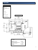
Stand diagrams PART#: SPMTRI/C MATERIALS USED: 12 (GA) CRS, Clear acrylic base COLOR: Silver A. Back plate B. Stand support C. Clear base D. Security access screws Dimensions are in Inch and mm E. (1) Cable access hole 18.25 (463.5) F. Fixed tabletop mounting holes 20.50 (520.7) 20.00 (508) 1.00 (25.4) 12 X 22 (304 x 558) MODEL PFM-32C1 FWD32LX1,FWD32DV1 PFM-42B1,PFM-42V1, FWD-50PX2 PFM-42LX1, FWD42DV1 PFM-50C1 PFM-50DV1 (A) A .37 (9.4) 1.0 (25.4) .72 (18.2) 1.0 (25.4) .90 (22.8) 1.0 (25.
Parts List TOOLS & SUPPLY NEEDED Phillips screwdriver HARDWARE (4) M5 x 10 (mm) flat head Phillip screws (4) Clear rubber feet (6) M5 x 30 (mm) flat head Phillip screws (2) M6 x 30 Phillips head screws (used on the 30” plasma only) (2) M5 x 12 (mm) phillip security screws (used on 42" and 50" plasma displays only) (2) #10 x 1-3/4" wood screws (Optional use) Building the stand Step 1 Unpack the components from the box and set them on the floor.
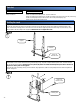
Securing the plasma to the stand Step 3 Raise the display with the securing sleeves installed to the plasma. Slip the sleeves through the four (4) keyholes on the back plate and drop it down slowly, make sure all of the four (4) sleeves are in the keyhole slot before letting go of the plasma. On the 42" and 50" two (2) M5 x 12 Phillip screws (security screws) can be used for additional security. See figure 3. NOTE: If using a 32” plasma, secure it with the two (2) M6 x 30 Phillip screws supplied.
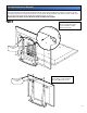
(Optional) fixed installation Step 1 Invert the stand and locate the two (2) mounting points on the bottom of the stand for (optional) fixed tabletop installation. Measure the distance between center to center of these two (2) holes and mark the table. See figure 4. NOTE: This diagram shows the bottom of the stand. Wood screw access holes Step 2 OPTIONAL TABLE MOUNTING If securing to a wood table, mark the table and drill properly. Secure the stand with the two (2) #10 x 1-1/4" wood screws (supplied).