SRP-X500P RS-232C Interface Manual Digital Powered Mixer SRP-X500P RS-232C Interface Manual 1st Edition Issued: Jan.
SRP-X500P RS-232C Interface Manual Table of Contents 1. OVERVIEW .............................................................................................................. 3 1.1 1.2 1.3 1.4 1.5 1.6 1.7 ABOUT THIS MANUAL ............................................................................................. 3 CONNECTING THE SRP-X500P TO A COMPUTER ..................................................... 3 COMMUNICATION FORMAT ........................................................................
SRP-X500P RS-232C Interface Manual 1. Overview 1.1 About This Manual This manual is the Interface Manual for the Sony SRP-X500P Digital Powered Mixer. The protocol explained in this manual is designed for controlling the SRP-X500P Digital Powered Mixer from an externally connected computer. This manual should be used together with the Operating Instructions and the User’s Guide.
SRP-X500P RS-232C Interface Manual 1.3 Communication Format The communication format is described below. Baud rate Communication mode Data length Parity bit Stop bit Flow control : 38,400 bps : Half-duplex start stop system (asynchronous) : 8 bits : odd : 1 bit : None 1.4 Communication Protocol The communication protocol is described below. ・When the SRP-X500P successfully receives a command from the computer, the SRP-X500P returns an ACK (Acknowledge).
SRP-X500P RS-232C Interface Manual NAK : 0x4E ( ‘N’ ) When the SRP-X500P fails to process a command sent by an external computer, it returns a NAK to the computer. DELIMITER : 0x0D ( ‘CR’ ) The SRP-X500P adds a delimiter code (equivalent to the ASCII carriage return) as the last byte of all commands. 1.7 Communication Packet Format Communication packets are variable in data length. A communication packet consists of command, parameter and delimiter, as shown below.
SRP-X500P RS-232C Interface Manual 2. Command Reference 2.1 Basic Control Commands The following commands are provided to perform basic control on the SRP-X500P such as volume level control and channel input selection. 2.1.1 AV/RGB INPUT SELECT : 0x43 0x53 0x45 0x4C (‘CSEL’) This command is used to select the channel input from the AV/RGB INPUT connectors (A to E). Packet format 0x43 0x53 0x45 0x4C “parameter” 0x0D ♦ Parameter The parameter consists of 1 byte of data, as shown in the following table.
SRP-X500P RS-232C Interface Manual Return packet format When the SRP-X500P receives a command successfully, the parameter is returned together with an ACK (0x41 (‘A’)) in the order shown below. 0x41 “parameter” 0x0D The parameter is the same as that of the AV/RGB INPUT SELECT command. Example When channel B input from among the AV/RGB INPUT connectors is selected 0x41 0x32 0x0D (‘A 2 CR’) 2.1.3 INPUT FADER : 0x43 0x50 0x4D 0x35 (‘CPM5’) This command is used to set the input fader setting.
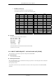
SRP-X500P RS-232C Interface Manual • FADER (1st-6th byte) The level for each fader can be specified (in dB units). The parameter and levels are as shown in the following table. Level -∞ -70.0 -60.0 -55.0 -50.0 -45.0 -40.0 -35.0 -32.5 -30.0 -27.5 -25.0 -24.0 -23.0 -22.0 -21.0 Level 0x30 (‘0’) 0x31 (‘1’) 0x32 (‘2’) 0x33 (‘3’) 0x34 (‘4’) 0x35 (‘5’) 0x36 (‘6’) 0x37 (‘7’) 0x38 (‘8’) 0x39 (‘9’) 0x3A (‘:’) 0x3B (‘;’) 0x3C (‘<‘) 0x3D (‘=‘) 0x3E (‘>‘) 0x3F (‘?’) -20.0 -19.0 -18.0 -17.0 -16.0 -15.0 -14.0 -13.
SRP-X500P RS-232C Interface Manual 2.1.5 OUTPUT FADER : 0x43 0x50 0x4D 0x40 (‘CPM@’) This command is used to set the level of the output faders. The parameter specified by this command functions in the same way as the output faders in the OVER VIEWscreen of the SRP-X500P Manager. Packet format 0x43 0x50 0x4D 0x40 “parameter” 0x0D ♦ Parameter The parameter consists of 8 bytes of data in the order shown in the following table.
SRP-X500P RS-232C Interface Manual Return packet format When the SRP-X500P receives the command successfully, the parameter is returned together with an ACK (0x41 (‘A’)) in the order shown below. 0x41 “parameter” 0x0D The parameter consists of 8 bytes of data and is the same as that of the OUTPUT FADER command. 2.1.7 REMOTE 1-6 LEVEL : 0x43 0x4C 0x56 0x4C (‘CLVL’) This command is used to set the level of the REMOTE faders. The level of the REMOTE faders are reset to 0 dB when the SRP-X500P is turned off.
SRP-X500P RS-232C Interface Manual • LEVEL (2nd byte) The level for each fader can be specified (in dB units). The parameter and the level are as shown in the following table. Level -∞ -70.0 -60.0 -55.0 -50.0 -45.0 -40.0 -35.0 -32.5 -30.0 -27.5 -25.0 -24.0 -23.0 -22.0 -21.0 Level 0x30 (‘0’) 0x31 (‘1’) 0x32 (‘2’) 0x33 (‘3’) 0x34 (‘4’) 0x35 (‘5’) 0x36 (‘6’) 0x37 (‘7’) 0x38 (‘8’) 0x39 (‘9’) 0x3A (‘:’) 0x3B (‘;’) 0x3C (‘<‘) 0x3D (‘=‘) 0x3E (‘>‘) 0x3F (‘?’) -20.0 -19.0 -18.0 -17.0 -16.0 -15.0 -14.0 -13.
SRP-X500P RS-232C Interface Manual ♦ Parameter The parameter consists of 7 bytes of data in the order shown in the following table. Byte Parameter 1st 2nd 3rd 4th 5th 6th 7th MASTER VOLUME LEVEL REMOTE 1 LEVEL REMOTE 2 LEVEL REMOTE 3 LEVEL REMOTE 4 LEVEL REMOTE 5 LEVEL REMOTE 6 LEVEL • MASTER VOLUME LEVEL (1st byte) The master volume level is shown (in dB units). The correspondence of the parameter with the level setting is the same as that of the FADER parameter of the INPUT FADER command (page 7).
SRP-X500P RS-232C Interface Manual 2.1.10 MASTER VOLUME DOWN : 0x43 0x4C 0x56 0x2D (‘CLV-’) This command is used to turn down the master volume. When this command is transmitted, the volume level decreases continuously. When the MASTER VOLUME STOP command (page 13) is transmitted, the volume level stops decreasing. To read the control status of the MASTER VOLUME motor from the SRP-X500P, use the STATUS REQUEST command (page 23).
SRP-X500P RS-232C Interface Manual 2.1.12 MUTING : 0x43 0x4D 0x55 0x54 (‘CMUT’) This command is used to turn off the specified channel (“Muting on”) or turn the channel back on (“Muting off”). The parameter specified in this command for the MIC 1/2/WL 1/2 INPUT, MIC 3/4 INPUT, LINE INPUT, AV/RGB INPUT, SPEAKER OUTPUT 1-4, and LINE OUTPUT 1-4 channels function in the same way as the MUTING buttons in the BLOCK screen and the OVER VIEW screen of the SRP-X500P Manager.
SRP-X500P RS-232C Interface Manual Example To turn off REMOTE fader 1(“Muting on”): 0x43 0x4D 0x55 0x54 0x42 0x41 0x0D (‘C M U T B A CR’) 2.1.13 MUTING PARAMETER REQUEST : 0x52 0x4D 0x55 0x54 (‘RMUT’) This command is used to read the muting status of the SRP-X500P. Packet format 0x52 0x4D 0x55 0x54 0x0D Return packet format When the SRP-X500P receives the command successfully, the parameter is returned together with an ACK (0x41 (‘A’)) in the order shown below.
SRP-X500P RS-232C Interface Manual • LINE OUTPUT MUTING (3rd byte) Shows the muting status of the LINE OUTPUT channels in the form of 8 bits of data. The bit is 0 for a channel which is not turned off (“Muting off”) and 1 for a channel which is turned off (“Muting on”). MSB bit7 0 • bit6 1 bit5 0 bit4 0 bit3 CH4 bit2 CH3 bit1 CH 2 LSB bit0 CH 1 MASTER MUTING (4th byte) Shows the muting setting of the master volume. The parameter and the muting setting are as shown in the following table.
SRP-X500P RS-232C Interface Manual 2.1.14 PROJECTOR ON/STANDBY : 0x43 0x50 0x4A 0x50 (‘CPJP’) This command is used to change the power status (on or standby status) of the projector connected to the PROJECTOR CONTROL connector. Packet format 0x43 0x50 0x4A 0x50 “parameter” 0x0D ♦ Parameter The parameter consists of 1 byte of data. Byte Parameter 1st PROJECTOR CONTROL REQUEST • PROJECTOR CONTROL REQUEST (1st byte) Specify the power status of the projector.
SRP-X500P RS-232C Interface Manual • PROJECTOR ON/STANDBY INDICATOR (1st byte) Shows the status of the PROJECTOR ON/STANDBY POWER switch. The parameter and the status of the PROJECTOR ON/STANDBY POWER switch are as shown in the following table. PROJECTOR ON/STANDBY INDICATOR STANDBY (The switch lights up red.) ON (The switch lights up red.) Cool off before entering STANDBY (the switch flashes green.
SRP-X500P RS-232C Interface Manual 2.1.17 SCENE RECALL PARAMETER REQUEST : 0x52 0x52 0x43 0x4C (‘RRCL’) This command is used to read the recalled scene number from the SRP-X500P. Packet format 0x52 0x52 0x43 0x4C 0x0D Return packet format When the SRP-X500P receives the command successfully, the parameter is returned together with an ACK (0x41(‘A’)) in the order shown below. 0x41 “parameter” 0x0D ♦ Parameter The parameter consists of 1 byte of data. Byte Parameter 1st SCENE No. • SCENE No.
SRP-X500P RS-232C Interface Manual 2.2 Status Acquisition Commands The following commands are used to acquire the settings and the status of the SRP-X500P. 2.2.1 INDEX REQUEST : 0x52 0x50 0x4D 0x44 (‘RPMD’) This command is used to read the index names of all input/output connectors of the SRP-X500P. The parameter returned for this command are the index names entered in the index name input boxes in the BLOCK screen of the SRP-X500P Manager.
SRP-X500P RS-232C Interface Manual Example When the input/output channels are specified with the index names as follows: MIC 1/WL 1 INPUT : MIC□1 MIC 2/WL 2 INPUT : MIC□2 MIC 3 INPUT : MIC□3 MIC 4 INPUT : MIC□4 LINE INPUT : MD AV/RGB INPUT A : CD AV/RGB INPUT B : DVD AV/RGB INPUT C : CASSETTE AV/RGB INPUT D : PC□1 AV/RGB INPUT E : PC□2 SPEAKER OUTPUT 1 : SP□1 SPEAKER OUTPUT 2 : SP□2 SPEAKER OUTPUT 3 : SP□3 SPEAKER OUTPUT 4 : SP□4 LINE OUTPUT 1 : AUX□L LINE OUTPUT 2 : AUX□R LINE OUTPUT 3 : REC□L LINE OUTPUT
SRP-X500P RS-232C Interface Manual ♦ Parameter The parameter consists of 16 bytes of data in the order shown in the following table.
SRP-X500P RS-232C Interface Manual Example When the level meter readings are as follows: MIC 1/WL 1 INPUT LEVEL METER MIC 2/WL 2 INPUT LEVEL METER MIC 3 INPUT LEVEL METER MIC 4 INPUT LEVEL METER LINE INPUT L LEVEL METER LINE INPUT R LEVEL METER AV/RGB INPUT L LEVEL METER AV/RGB INPUT R LEVEL METER SPEAKER OUTPUT 1 LEVEL METER SPEAKER OUTPUT 2 LEVEL METER SPEAKER OUTPUT 3 LEVEL METER SPEAKER OUTPUT 4 LEVEL METER LINE OUTPUT 1 LEVEL METER LINE OUTPUT 2 LEVEL METER LINE OUTPUT 3 LEVEL METER LINE OUTPUT 4 LEVE
SRP-X500P RS-232C Interface Manual To acquire the status of all items Transmit the following command to acquire the status of all items available using the STATUS REQUEST command. Packet format 0x52 0x41 0x53 0x54 0x0D (‘R A S T CR’) Return packet format When the SRP-X500P receives the command successfully, the parameter is returned together with an ACK (0x41(‘A’)) in the order shown below.
SRP-X500P RS-232C Interface Manual Parameters The parameter consists of 108 bytes of data, as shown in the following table.
SRP-X500P RS-232C Interface Manual ♦ PROJECTOR PROTOCOL SWITCH (1st byte) SYSTEM TYPE SWITCH (2nd byte) Shows the position of the PROJECTOR PROTOCOL selector or the SYSTEM TYPE selector on the front panel of the SRP-X500P. The parameters and the switch position are shown in the following table.
SRP-X500P RS-232C Interface Manual ♦ INPUT LEVEL (16th-21st byte) Shows the value indicated by the yellow triangular marker at the side of the input fader in the OVER VIEW screen of the SRP-X500P Manager. This value is calculated using the input volume parameter, input fader parameter, master volume level parameter, and remote fader 1-6 parameters and this indicates the total input level value. The INPUT LEVEL parameter consists of the 6 bytes of data in the order shown in the following table.
SRP-X500P RS-232C Interface Manual ♦ OUTPUT MUTING (31st and 32nd byte) Shows the muting status of the output channels. The OUTPUT MUTING parameter consists of the 2 bytes of data in the order shown in the following table. • Byte Parameter 1st 2nd SPEAKER OUTPUT MUTING LINE OUTPUT MUTING SPEAKER OUTPUT MUTING Shows the muting status of the speaker output channels in the form of 8 bits of data.
SRP-X500P RS-232C Interface Manual ♦ RF/AF INDICATOR (36th byte) Shows the status of the RF and AF indicators on the front panel of the SRP-X500P in the form of 8 bits of data. The bit is 0 for indicators that are turned off and 1 for indicators that are turned on. MSB bit7 0 bit6 1 bit5 0 bit4 0 bit3 WL 2 AF bit2 WL 2 RF bit1 WL 1 AF LSB bit0 WL 1 RF ♦ WL INDICATOR (37th byte) Shows the status of the WL indicators in the form of 8 bits of data.
SRP-X500P RS-232C Interface Manual ♦ LINE TRIM (43rd byte) Shows the setting of the TRIM controls for the LINE input on the front panel of the SRP-X500P (in dBu units). The parameter and the TRIM control setting are shown in the following table.
SRP-X500P RS-232C Interface Manual ♦ FR (50th-53rd byte) The FR parameter consists of the 4 bytes of data in the order shown in the following table. • Byte Parameter 1st 2nd 3rd 4th MIC 1/WL 1 FR MIC 2/WL 2 FR MIC 3 FR MIC 4 FR FR Shows the status of the FEED BACK REDUCER. The correspondence of the parameter with the FEED BACK REDUCER setting is shown in the following table.
SRP-X500P RS-232C Interface Manual • SETUP STATUS Shows the progress of the FEED BACK REDUCER setting. The parameter and the progress are as shown in the following table.
SRP-X500P RS-232C Interface Manual ♦ IR OUTPUT MODE INDICATOR (59th byte) Shows the status of the IR OUTPUT MODE button on the front panel of the SRP-X500P. The correspondence of the parameter with the IR OUTPUT MODE button status is shown in the following table. IR OUTPUT MODE Normal operation (The button is turned off.) Transmission wait status (The button lights up.) Transmission in progress (The button flashes.
SRP-X500P RS-232C Interface Manual ♦ TEMPERATURE (78th and 79th byte) The TEMPERATURE parameter consists of 2 bytes of data in the order shown in the following table. • Byte Parameter 1st 2nd SPEAKER OUTPUT CH1/2 TEMPERATURE SPEAKER OUTPUT CH3/4 TEMPERATURE TEMPERATURE Shows the temperature of the heat sink in the power amplifier section. The correspondence of the parameter with the temperature is shown in the following table.
SRP-X500P RS-232C Interface Manual ♦ SCENE No. (84th byte) Shows the scene number to be recalled. The parameter and the scene number are shown in the following table. SCENE No. None 1 2 3 4 5 6 7 8 0x30 (‘0’) 0x31 (‘1’) 0x32 (‘2’) 0x33 (‘3’) 0x34 (‘4’) 0x35 (‘5’) 0x36 (‘6’) 0x37 (‘7’) 0x38 (‘8’) ♦ PARALLEL INPUT (85th-94th byte) The information on the input pins of the REMOTE PARALLEL connector is provided using 10 bytes of data in the order shown in the following table.
SRP-X500P RS-232C Interface Manual • OUTPUT 1-6 Shows the on/off status of output pins 1 to 6 of the REMOTE PARALLEL connector in 8 bits of data. When an output pin is off, the corresponding bit is 0, and when an output pin is on, the corresponding bit is 1. MSB bit7 0 • bit6 1 bit5 OUT6 bit4 OUT5 bit3 OUT4 bit2 OUT3 bit1 OUT2 LSB bit0 OUT1 OUTPUT 7-10 Shows the on/off status of output pins 7 to 10 of the REMOTE PARALLEL connector in 8 bits of data.
SRP-X500P RS-232C Interface Manual ♦ GAIN REDUCTION (99th-108th byte) The GAIN REDUCTION parameter consists of the 8 bytes of data in the order shown in the following table.
SRP-X500P RS-232C Interface Manual • COMPRESSOR GAIN REDUCTION Indicatess the gain reduction level reading of the COMPRESSOR (in dB units). The parameter and the gain reduction level reading are shown in the following table.
SRP-X500P RS-232C Interface Manual 2.3 Maintenance Information Commands The following commands are provided to read and write the information on the SRP-X500P and to restore the parameters to their factory default settings. 2.3.1 INFORMATION REQUEST : 0x52 0x50 0x4D 0x45 (‘RPME’) This command is used to read information from the SRP-X500P. The parameter that is shown for this command are the contents entered in the INFORMATION input section in the PANEL VIEW screen of the SRP-X500P Manager.
SRP-X500P RS-232C Interface Manual 2.3.2 MAINTENANCE INFORMATION READ WRITE : 0x43 0x4D 0x49 0x31 (‘CMI1’) This command is used to enter information in the 256-byte readable/writable area in the maintenance information memory of the SRP-X500P. You can use this area to enter information such as the room name and the date and time when the SRP-X500P was set up.
SRP-X500P RS-232C Interface Manual 2.3.3 MAINTENANCE INFORMATION READ WRITE REQUEST : 0x52 0x4D 0x49 0x31 (‘RMI1’) This command is used to read the information entered in the 256-byte readable/writable area in the maintenance information memory of the SRP-X500P. Packet format 0x52 0x4D 0x49 0x31 0x0D Return packet format When the SRP-X500P receives the command successfully, the parameter is returned together with an ACK (0x41(‘A’)) in the order shown below.
SRP-X500P RS-232C Interface Manual Example When the RMI2 command is received: 0x41 0x53 0x52 0x50 0x2D 0x58 0x35 0x30 0x30 0x50 0x20 0x20 0x20 0x20 0x20 0x20 0x20 0x20 0x20 0x20 0x20 0x20 0x20 0x20 0x20 0x20 0x20 0x20 0x20 0x20 0x20 0x20 0x20 0x20 0x20 0x20 0x20 0x20 0x20 0x20 0x20 0x20 0x20 0x20 0x20 0x20 0x20 0x20 0x20 0x20 0x20 0x20 0x20 0x20 0x20 0x20 0x20 0x20 0x20 0x20 0x20 0x20 0x20 0x20 0x20 0x20 0x20 0x20 0x20 0x20 0x20 0x20 0x20 0x20 0x20 0x20 0x20 0x20 0x20 0x20 0x20 0x20 0x20 0x20 0x20 0x20 0x2
SRP-X500P RS-232C Interface Manual Example When the version is 1.00 0x41 0x31 0x2E 0x30 0x30 0x20 0x20 0x20 0x20 0x20 (‘A 1 . 0 0 □ □ □ □’) “□” indicates a space. 2.3.6 FACTORY PRESET : 0x43 0x52 0x53 0x54 (‘CRST’) This command is used to restore the parameters of the SRP-X500P to their factory default setting. When this command is transmitted, all parameters of the SRP-X500P return to their factory default setting, including the scene memory settings.