Video Projector Operating Instructions BRAVIA H ii:::ll!11'1111 TM HIGH-O FINITION MULTIMEDIA INTERFAGE VPL-AW15 VPL-AW10 © 2007 Sony Corporation
Declaration WARNING To reduce the risk of fire or electric shock, do not expose this apparatus to rain or moisture. To avoid electrical shock, do not open the cabinet. Refer servicing qualified personnel only. to =m,=/k CAUTION: TO REDUCE DO NOT THE REMOVE RISK COVER NO USER-SERVICEABLE REFER SERVICING rO QUALIFIED OF ELECTRIC (OR SHOCK, BACK}, PARTS INSIDE, SERVICE PERSONNEL.
Disposal of Used Lamp This prc_iector's lamp contains mercury and should be disposed of properly. Consult your local authorities regarding safe disposal. The material contained in this lamp are similar to those of a fluorescent lamp, so you shoukt dispose of it in the same way. For customers in the United States Lamp in this product contains mercury. Disposal of these materials may be regulated due to environmental considerations.
For customers in Canada This Class B digital apparatus Canadian ICES-003. complies with Voor de klanten in Nederland lever deze in als klein chemisch al\,al Gooi (KCA). de batterij niet weg maar The socket-outlet shoukt be installed near the equipment and be easily accessible. CAUTION RISK OF EXPLOSION IF BATTERY IS REPLACED BY AN INCORRECT TYPE. DISPOSED OF USED BATTERIES ACCORDING TO THE LOCAL RULES.
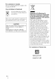
Table of Contents Precautions ......................................... 7 the model name of the ............................................. 7 Projecting the Picture on the Screen .............................................. Front/Side ........................................... 8 Selecting Rear/Bottom ....................................... 9 Remote Control ................................ 10 Selecting the Picture Viewing Mode ...............................................
Troubleshooting ............................... Warning Indicators Message Lists Replacing ..................... ............................. 51 53 54 the Lamp and the Air Filter and cleaning the Ventilation holes (intake) ............................................. 55 Replacing 58 Fitting the Air Filter ................... the lens cap ........................... Specifications ................................... Preset Signals .............................
Precautions On safety • Check that the operating voltage of your unit is identical with the voltage of your local power supply. • Should any liquid or solid object fall into the cabinet, unplug the unit and have it checked by qualified personnel before operating it further. • Unplug the unit from the wall outlet if it is not to be used for several clays. • To disconnect the cord, pull it out by the plug. Never pull the cord itself. • The wall outlet shouM be near the unit and easily accessible.
Front/Side You call use the buttons on the control panel with the same names as those on the remote control to operate the projector. LAMP/ COV_R LAMP/COVER indicator ((_ page 53) @--- While the I/0) (On/ standby) indicator lights in orange, the power saving mode is on.
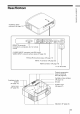
Rear/Bottom r-- o ¢b 9) O o © o Ventilation (exhaust) holes ((_ page Connects to a computer, etc.
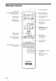
Remote Control Infrared LIGHT button Illuminates the buttons on the remote control. INPUT button (_ page 27) FREEZE button ((_ page 35) transmitter --, ..... I/(_ (On/standby) switch ((_ page 22) ..................... ................... PIC MUTING button ((_ page 35) ................................. APA button -- RESET ((_ page 48) button ((_ page 39) "t/_.
This section describes how to install the projector and screen, how to connect the equipment from which you want to project the picture, etc. 0 © o Unpacking Q_ "U Check the carton to make sure it contains the following items: • Lens cap (1) When you have purchased the projector, the lens cap was litted onto the lens. Remove this lens cap when you use the projector.
Step 1: Installing the Projector The proiector displays pictures a VCR or other devices. output front Near a heat or smoke sensor The pro}ector can be used in various places and you can enjoy viewing beautiful pictures easily. iiiiiii i,ilil Malfunction Unsuitable installation Do not place the projector in the following situations, which may cause malfunction or damage to the projector. of the sensor may occur.
Improper use Do not do any of the following while using the projector. © Blocking the ventilation holes. o 15° or more o Ventilation holes (intake) _/entilation holes (exhaust) Tip For details on the location of the ventilation holes (intake or exhaust), see "Location Controls" on pages 8 to 9. Tilting front/rear of and left/right Avoid using the proiector tilted at an angle of more than 15 degrees. Do not install the projector anywhere other than on a level surface or on the ceiling.
The installation of the screen. distance between the projector and a screen varies depending Determine the installation position You call obtain a good quality picture if the lens within the areas indicated in the only). Use the values a, b, c and d in the on the size of the projector and screen. you position the projector with the center of gray areas in the illustration (VPL-AWI5 table on page 15 as a guide.
When using the 16:9 aspect ratio screen Unit: mm Screen size (inches) (mm) 40 60 70 80 100 120 140 160 180 (inches) 200 © o 1016 1524 1778 2032 2540 3048 3556 4064 4572 5080 a (lllillilllUm) 1151 (45 3Is) 17511 !69) 2049 (801Ih61 2348 (92 I/2) 2946 1116) 3544 (1395/8) 4142 11631/8) 4740 11863/4) 5339 (2101/4) 5937 12337/8) b (maximum) 1885 (74 1/4) 2849 (1121/4) 3332 (131 1/4) 3814 (1501/4) 4779 (188 1/4) 5744 (2261/4) 6709 (21¢11/4) 7673 8638 13/121/8) (34/11/8) 960
2 Position the projector so that the lens is parallel to the screen. Top view Screen 3 Project an image on the screen and adjust the picture so that it fits the screen. (_ page 21) To project an image, connect video equipment to the projector. ((_" page 17) ] I_mlFa When using a screen with an uneven surface, stripes pattern may rarely appear on Ihe screen depending on the distance belween the screen and the projeclor or the zoeming magnifications. is not a mallunction of the projeclor.
Step 2: Connecting the Projector When making connections, be sure to do the following: • Turn off all equipments before making any connections. • Use the proper cables for each connection. • Insert the cable plugs properly; poor connection at the plugs may cause a malfunction or poor picture quality. When pulling out a cable, be sure to pull it out with holding the plug, not the cable itself. • Refer to the operating instructions of the connected equipment.
To connect to a DVD player/recorder equipped with HDMI output and Blu-ray Disc player You call enjoy better picture quality by connecting a DVD player/recorder and Blu-ray Disc player equipped with HDM! output to the HDM! input of the projector. AV amplifier Rear of the projector L - Speakers © DVD player/recorder Blu-ray Dis_player, I P_/¢_ with the HDMI output L NPUTA and etc.
To connect to a VCR equipped video connector with the S video connector or You call connect a DVD player/recoMer, haM disk video recoMer, VCR o1"laser disk player, which is not equipped with component video connectors, See also the instruction manual of each equipment.
Rear of the projector Computer ++._c. ,_ to monitor output HD-Dsub15 pin cable (optional) or HDMI cable (optional) u:_&+++: Video signal flow When using an optional HDMI cable, be sure to use a cable that has acquired an HDMI logo. Tip Set "lnput-A Signal Sel." inthe Setup _ not appear properly, set it to "Computer." menu to "Aote" or "Computer.
Step 3: Adjusting the Picture Position tS"oject an image on the screen and then at[just the picture position. C3 o 1 i1¢(On/standby)indicator (/) O_ 6, 7 5 -0 Zoom lever, Focus ring X3 LENS SHIFT dials (VPL-AW15 only) Remote control detector o (/) REALCOLO_PROCB_I_G Tip The I/(,D (On/standby), INPUT, MENU, and A/V/_I/I_I@ (ieystick) prejeclor lUllCtioa the sanle as those (111tile remote COlltrol. buttons on the top panel ol the [I_NF.
@ 2 Press the I/@ (On/standby) switch to turn on the projector. The I/@ (On/standby) indicator flashes ill green, and then lights ill green. 3 Turn on the equipment connected to the projector. k Flashes in green for a few seconds, and then lights in green. Refer to the operating the connected 4 instructions of equipment. Press INPUT to project the picture on the screen. Each time you press the button, the input indication and equipment to be projected change.
To adjust the horizontal position Turn the LENS SHIFT dial right o1"left. The picture projected on the screen moves right or left by a maximum of 25% of the screen size fi'om the center of the lens. 25% I 1 screen width I © 25% I © I Top view o c/) 9) O_ 9) © c/) : Picture position at maximum when moving : Picture position when right at maximum To adjust the vertical moving the picture to the left the picture to the position Turn the LENS SHIFT dial up o1"down.
6 Adjust the picture size using the zoom lever. Zoom lever 7 Adjust thefocus using thefocus ring. Focus ring To adjust the tilt of the installation If the projector level. surface is installed on an uneven surface, use the a_[justers to keep the projector Adjusters Be careful uol lo catch your linger when lurning Ihe adjusters.
Step 4: Selecting the Menu Language You call select one of l6 languages for displaying the menu and other on-screen displays. The factory default setting is English. To change the current menu language, set the desired language with the menu screen. © © (/1 Q_ "0 © u) ..... 2, 3, 4 °'-- 1 1 Press MENU. The menu appears.
2 Press till, to select the Setup menu, and press =1_ or @. The setting items of the selected menu appears. m 3 Press till, to select "Language," and press =1_or @. 4 Press t/l[,/'l=/=l_ to select a language, and press @. The menu changes to the selected language. To clear the menu tS"ess MENU.
This section describes how to operate the projector to view the picture from the equipment cmmected to the projector. It also describes how to a_!just the quality of the picture to suit your taste. "0 5" Projecting the Picture on the Screen Power on both the equipment and the device connected to the equipment. 2 Press INPUT repeatedly to select the input you want on the screen. to project Display waut.
1 Press the I/(_ (On/standby) switch. A message "POWER OFF'?" appears on the screen. 2 Press the I/_ (On/standby) switch again before the message disappears. The I/(_ (On/standby) indicator flashes in green and the fall continues to run to reduce the internal heat. First, the I/(_ (On/standby) indicator flashes quickly, during which you will not be able to light up the I/(_ (On/standby) indicator with the I/(_ (On/standby) switch.
Original image When the Wide Mode is operated Wide Zoom A 4:3 aspect ratio picture is enlarged over the entire screen properly. The upper and lower portions of the screen are slightly cut off. -0 o 5 Normal A picture with normal 4:3 aspect ratio is displayed ill the center of the screen to fill the vertical screen size. Full Squeezed A picture squeezed to 4:3 is displayed with the correct aspect ratio. A 4:3 picture is enlarged horizontally to fit the 16:9 screen.
Full 2 (When the PC signal is input) Displays a picture on the whole of the screeu, ] I_mlTa You can adjust the vertical position ollhe picture with "V Center" and "Vertical menu only when "Zoom" is selected. ((_ page 45) Notes on selecting the wide screen Size" in the Screen mode The projector is featured with the WIDE MODE. Wheu changing the settings of WIDE MODE, it must be noted as below.
Selecting the Picture Viewing Mode You call select the picture viewing mode that best suits the type of program o1"room conditions. Press one of the PICTURE MODE buttons (DYNAMIC, STANDARD, CINEMA and USER 1, USER 2 and USER 3). DYNAMIC R_L COLOR _ROCESSlNG WIDE Enhauces STANDARD pICTt*_EMOD_ _1 ..... II..... 1 "-RCP butlon: VPL-AW 15 only picture contrast and sharpness.
Adjusting the Picture Quality You can at[just the picture quality that suits your taste by selecting the ac!justment items with the remote control. The ac!justed data can be stored in each picture mode. Press Each r-s_ r_n F;_ ADJ time PIC. you press the button, the following at{justment windows* are displayed in sequence. * Some of the above adjustment windows will not be displayed depending oil the input signal. For details, see "Input Signals and Adjustable/Setting Items.
Adjusting the Picture Using Real Color Processing (VPL-AW15 only) The Real Color Processing (RCP) feature allows you to at[just the color and hue of each target of the projected picture you specify independently. You call thus obtain a picture more suitable to your taste. Tip Freeze Ihe scene of the video source when you are adjusting the picture asing Real Color Processing. 1 Press RCP on the remote control. 2 Press '1'/41,to select "User 1," "User 2" or "User 3," then press ,._.
I_ Press t/lJ, "Range," to select and specify "Position" or it more delicate color position and color range you want to at!just using '4,,,,/,-,1_. 4 Adjust the color of the specified portions. Press t/_" "RCP Hue," to select "RCP Color" then at!just or the color or hue of the portions selected ill step 3 to suit your taste using '4,,,,/,,,_ while watching the projected picture. The picture is returned to normal color during 5 at!iustment. After the adjustment is complete, press @.
Using Other Functions You call temporarily turn off o1"pause a projected picture. Press PIC MUTING. --- PIC MUTING button ....... FREEZE button ]Press to temporarily turn off a projected picture. To return to the previous screen, press PIC MUTING again. Press FREEZE. A projected picture can be paused to be displayed. "FREEZE" is shown on the screen when a button is pressed. To return to the previous screen, press FREEZE again. REALe0LORP_0CESSI_G Available for only computer signal.
This section describes how to make various at[iustments and settings using the menus. Operation through the Menus The projector is equipped with an on-screen menu for making various adjustments and settings. Some of the ac!iustable/setting items are displayed ill a pop-up menu, in a setting menu or adjustment menu with no main menu, or in the next menu window. If you select an item name followed by an arrow (IP-),the next menu window with setting items appears.
1 Press MENU. The menu window appears. C u) i¸i!il;iiiii;;!iiil}iiiii ¸iiii ¸iiii ¸iiii ¸iiii ¸iiii ¸iiii ¸iiii ¸iiii ¸iiii ¸iiii ¸iiii ¸iiii ¸iiii ¸iiiii!!!i_ii_!!!)i_ii_i_!ii!!ii_i_i;_J 2 i i_g;_w_ Press til!, to select a menu item, and press --I_ or @. The items that call be set or adjusted with the selected menu appear. The item presently selected is shown ill yellow.
3 Pop-up menu Setting items Nededands ¢;_1_) Deutscb s_qu'lZ_ Porluga6s Svenska ® Setting menu Standard C_nema User1 User2 Users Adjustment menu Next menu window Setting Cinema items Black Pro i s @ Menu window 38 of VPL-AW15) Press _/,!, to select an item you want to set or adjust and press _'or @. The items that can be set appear in the pop-up menu, setting menu, adjustment menu, or in the next menu window.
4 Make the setting or adjustment of an item. To reset the items that have When changing the adjustment level To increase the value, press t/=l_ ". To decrease the value, press _,/_. _'ess @ to restore the previous screen. Select all item in the Menu screen, and display the pop-up menu, the setting menu, and the adjustment menu. tS"ess the RESET on the remote control to reset only the selected settings to its factory preset value. When changing the setting Press t/l[, to change the setting.
Picture Menu The Picture menu is used for ac[justiug the picture. Adjust Picture menu J I I J Picture Mode J ] } J J ] J You can select the picture viewing mode that best suits the type of picture or the environment. Dynamic: Select Ihis lk)renhauced piclure contrast and sharpness to reproduce color tones. Standard: Select this tu reduce roughness compared to viewing the picture with Dynamic. Cinema: Select this for watching movies, etc. in a dark environment.
Cinema BlackPro Advanced Iris Switches the iris function VPL-AW15 during projection. Auto 1: .Automatically switches to an optimum iris according to a projected scene. The contrast of the scene is emphasized most. Auto 2: An optimum iris becomes smaller than when set to "Auto 1". The contrast of the scene becomes reduced. Sensitivity: If "Auto 1" or "Auto2" is selected, "Fast", or "Slow" can be selected according speed with Sensitivity Mode. Manual: Manually adjusts the Iris.
Sharpness Sharpens the outline of the picture, or reduces the noise. Tile higher the setting, the stmrper the picture. The lower the setting, the softer the picture, thus reducing the noise. NR(NoiseReduction) Reduces the roughness or noise of the picture. Usually, select "011". If tt_epicture is rough or noisy, select a setting from among "Low", "Middle" or "High" according to the input signal source.
Advanced The Advanced Picture Picture Menu (VPL-AW15 is used for a_!justing the picture only) more. C q) ¢Q N; ij ® c u) RCP(Real Color Processing) VPL-AW15only) You can adjust the color and hue of each selected portion of the picture independently. User 1, User 2, User 3: You can adjust the picture using Real Color Processing and store the settings. Once the settings are stored, you can view the picture with the adjusted picture quality. Off: Cancels this feature.
Screen Menu The Screen menu is used to adjust the input signal. You call at!just the size of the picture, and select wide screen mode, etc. Adjust Screen menu J I ® i)il¸I¸I¸I¸¸II¸I¸¸II¸I¸I¸¸II¸I¸I¸¸II¸I¸¸II¸I¸I¸¸II¸I¸I¸!_ji!_!i!_i_i_iii;i_INi_i_iii_ Wide Mode (Whenthe You can set the aspect ratio of the picture to be displayed for the inputsignalis moving current input signal. This item is enabled only when a moving picture) picture (preset memory numhers 1 to 14) (_" page 61) is provided.
ScreenArea Selects the size of the picture when a Hi-Vision picture is overscanned. Full: Expands the picture ou ttle wtlole off the screen. Through: Does not expands the picture on the whole ol the screen. This item is effective only when a Hi-Visiou signal (preset memory No. 10 and 1l ) is input and "O11" is selected in "Over Scan". V Center Adjust the whole picture by moving up and down on the screen.
Setup Menu The Setup E_ menu :::::::::::::::::::::::::::: _ _i ! is used to chan e the factory Standard J Slandard ] on compu*er } AUto J preset settings, etc. iiiiiiiiiiiiiiiiiiiiiiiiiiiiiiiiiiiiiiiiiiiiiiiiiiiiiiiiiiiiiiiiiiiiiiiiiiiii!1 a_ ¢ Status Sets whether or not the on-screen display is displayed. Set to "OFP' to turn ()It"tile on-screen displays except lkw the menus, message when turning oil tt_e power, and warning messages.
Inpnt-ASignal Sel. Selects the type of signal input from the equipment the INPUT A connector. connected to Selects the type of signal input fl'om the equipment by selecting "lnput-A" with the INPUT. Auto: Selects the input signal type automatically. Computer: lnputs the signal fl'om a computer. Video GBR: Inputs the signal [)'ore a TV game or HDTV broadcast. Component: lnputs the component signal fi'om a DVD player/ recorder. Blu-ray Disc player, digital tuner, etc.
Function Menu The Function menu is used for changing the settings of the various functions of the projector. SmartAPA With this item set to On, the APA function works automatically for a signal input from a computer so that the picture can be seen clearly. You can also activate the APA function by pressing the APA on the remote control. Tip The APA (Auto Pixel Alignment) automatically adjusts the input signal from a computer so thai the picture can be seen clearly.
Installation The Installation '" menu Menu is used for changing the installation settings. ii C c/) cO @ V Keystone ¢) c 69 Corrects the vertical trapezoidal distortion of the picture. When the bottom of the trapezoid is longer than the top (/-_ Sets a lower value (- direction) When the top of the trapezoid is longer than the bottom Sets a higher value (+ direction).
Information Menu The Information menu displays the model name, serial number, the horizontal and vertical frequencies of the input signal and the cmnulated hours of usage of the lamp. rma*i_ i m M o d el N a m e: V P L -AW 15 o r V P L- AW 10 Mo_e,. ..... Serial -- SerialNo, NO. 15.73 kHz / 59.94 Hz ,,,,,,MemoryNo. fH/fV NI I amp Signaltype Timer Model Name Displays the model name (VPL-AWI5 or VPL-AWI0) and the serial number. Serial No. Displays the serial number.
This section describes etc. how to solve the problems, how to replace the lamp and air filter, Troubleshooting If the projector appears to be operating erratically, try to diagnose and correct the problem using the following instructions. If the problem persists, consult with qualified Sony personnel. Power Symptom Tile power is not turned on. CauseandRemedy + Alter about 1 minute, turn the power on. + Close the lamp cover securely, then tighten the screws securely.
Symptom CauseandRemedy The picture is too dark. + Adjust the coutrast or brightness of the Picture _ properly. (_ page 41 ) The picture is not cleat: + Adjust the focus using the R>cusring. ((_" page 24) + Condensation has accumulated on the lens. Leave the projector lk)rabout 2 hours with the power on. The picture flickers. + Activate "APA", then adjust the curreut input signal. + Adjust "Phase" for "Adjust Signal" in the Screen _ properly.
The I/@ (On/standby) or LAMP/COVER trouble with your projector. indicator lights up or flashes if there is any LAMP/ COVER @.,,,,,,,,,,,,,,,,,,,,,,,,,,,,,,,,,,,,,,,,,,,,, LAMP/COVER I/(_) (On/standby) Symptom indicator o indicator Z3- Cause and Remedy LAMP/COVER flashes in red. (A repetition rate of 2 flashes) -> Close the hm]i_ cover securely, then tighten the screws securely. ((_ page 56) -> Close the air filter cover securely. ((_ page 57) LAMP/COVER flashes in red.
Warning messages Message Cause and Remedy High temp.! Lamp oil' in 1 rnin. + Turn o11"the power. -) Check to ensure that nothing ((_" page 13) Frequeucy -) Frequency acceptable is out of range ! is blocking the ventilation holes. is out of range, lnput a signal that is within the li'equency range of the projector. Please check lnput-A Signal Sel. -) Sel "lnpuI-A Signal Sel." in the Setup _ menu to "Computer" when an RGB signal is input fi'om a computer.
1 Turn off the projector and unplug Replacing the Lamp and the Air Filter and cleaning the Ventilation holes (intake) the AC power cord. 2 When setting the projector on a flat surface such as a desk etc., put a cloth to prevent the surface from being scratched. Reverse the projector as illustrated, then place it on the cloth. Tools you need to get started: Standard Phillips screwdriver Cloth (for scratch protection) The lamp used for the light source has a certain lifespan.
4 Loosen the three screws on the 6 Close the lamp cover, then lamp with the Phillips screwdriver. Hold up the handle, then pull the lamp straight out. 5 Hold the handle of the new lamp and push it in securely until it reaches the end, and then tighten the 3 screws. • Be carelul not to touch the optical block inside the unit. • lfthe 3 screws are not tightened securely, the lamp cover will not close. 56 tighten the screws. lfthe lamp cover is uot sel securely, the power will nol turn on.
9 Place a new air filter. 13 Turn on the projector, then select the desired setting item on the Setup _ menu. The menu screen below will be appeared. Has the proiection Se[llngs for lamp lamp been replaced ? replacement ] 14 Select "Yes". o 33- After removing the air lilter, do not touch the fan inside the prujeclor. i Lamp replacement process is now complete. ] 10 Attach the air filter cover. 11 Wipe dust off the Ventilation holes (intake) with a soft cloth. 15 Select "OK".
Replacing the Air Filter Fitting the lens cap When "Please replace the filter." appears on the screen, you should replace the air filter. The air filter should be replaced every 1,500 hours. This value varies depending on the environment or how the projector is used. 1,500 hours are approximate. • For details on how to attach and remove on the air filter, see "Replacing the Lamp and the Air Filter and cleaning the Ventilation holes (intake)" Steps 7 to 11.
Specifications System Projection systmn 3LCD panel. 1 lens. 3 primary color LCD shutter projection system LCD panel 0.73-inch ( 18.5 ram) TFT LCD panel 2.764.800 pixels (921.600 pixels x 3) Lens 1.6 times zoom lens (manual) 1=21.3 to 34.1 mm/F2.4 to 3.1 Lamp 165 W Ultra High Pressure Lamp Prqjection picture size 4(1 to 200 inches (measured diagonally) Color system NTSC35dPAL/SECAM/NTSC44J PAL-M/PAL-N/PAL60 syste m.
Supplied accessories Remote control RM-PJAWI5 (1) (VPL-AW 15 only) RM-PJAWI0 (1) (VPL-AW 10 only) Size AA (R6) batteries (2) AC power coM (1) Air filter (for replacement) (1) Lens Cap (1) Operating Instructions (1) Design and specifications without notice.
Warning on power connection Use a proper power cord for your local power supply.
Memory No. Preset signal (Resolution) fH (kHz) fV(Hz) Sync H Size 9 1080/24PsF 1080/48i (1920 x 1080i) 27.000 48.000 SonG/Y 1(} 720/60p 720/60p (1280 x 720p) 45.000 60.000 SonG/Y 11 720/50p 720/50p (1280 x 720p) 37.500 50.000 SonG/Y 12 1080/60p 1080/60p (1920 × 1080p) 67.500 60.000 13 1080/50p 1080/50p (1920 × 1080p) 56.260 50.000 ]4 1080/24p 1080/24p (1920 x 1080p) 26.973 23.976 21 64(1 x 35(1 VGA-I 31.469 70.086 H-pos, V-neg 800 37.861 85.
Memory No. Preset signal (Resolution) fH (kHz) fV(Hz) Sync H Size 5O 1400 × 1050 SXGA + 65.317 59.978 H-neg. V-pos 1864 55 1280 × 768 1280 × 768/60 47.776 59.870 H-neg. V-pos 1664 56 1280 × 720 1280 × 720/60 44.772 59.855 H-neg. V-pos 1664 Preset memory numbers for each input signal Analog signal Signal Preset memory number Video signal (VIDE() INPUT and S VIDEO INPUT connectors) 1.
Some of the items in the menus cannot be adjusted depending on the input signal. The following tables indicate them. The items that cannot be adjusted are not displayed ill the menu.
Screen menu Item Input signal Video or S-Video (Y/C) Component Video GBR Computer Wide Mode • • • •,,,2 Over Scan - • Screen Area ,,I _ • - • (preset memory numhers 10. 11 • (preset memory numbers 10. 11 _ only) only) V Position .3 • • • • V Size .3 • • • - APA - •,4 Phase - •,4 Pitch - •,4 Shift - o Z3- • • • • : Adjustable/can be set - : Not adjustable/cannot be set ,1: This item is ellective only when "Over Scan" is set to "On" in the Screen _ menu.
Ceiling Installation Use the PS S-H 10 o1"PS S-610 Projector Suspension Support when you install the projector on a ceiling. The projection distances for ceiling installation ;ure shown below.
When using the 16:9 aspect ratio screen Unit: mm (inches) I 60 70 80 lOO 120 140 160 1524 1778 2032 2540 3048 3556 466445725080 I Minimum 1266 Distance (49 7/8) 1864 2163 2462 (97) 306 I 3659 4257 4855 ( 120 5/8) (144 1/8) ( 167 5/8) (1911&) Maximum 1999 Distance 2964 (116 3&) 3446 (135 3929 4894 (154 3/4) ( 192 3h) 5858 6823 7788 (3t)6 3&) 8753 0717 (344 3&) (382 _) Minimum 249 Distance 373 (14 3/4) 436 (17 1/4) 498 (19 5/8) 747 871 (34 3&) 996 (39 l&) 1121) (44 1/8) M
Attaching the PSS-HIO projector suspension support For details on installation on a ceiling, refer to the Installation manual for Dealers of the PSS-HIO. Make sure to consult with a qualified Sony personnel for installation. The installation measurements are shown below when installing the projector on a ceiling using the PSS-HIO. Top view Install the projector so that the center of the lens is parallel to the center of the screen.
Front view Ceiling Center of the supporting pole 175(7) The bottom surface of the mount bracket o C]- d) Center of the lens *d 63.5 (2 1/_) (VPL-AWI5) 68 (2 3/4)-(VPL-AW 10) Side view 1t4.5(45/8) l ............. Center 130(5 ;/B) .......................... { of the lens (VPL-AW15 Front of the cabinet only) ......
a: Distance between the screen and the installation hole of the upper ceiling mount bracket (front side) b: Distance from the ceiling to the bottom surface of the unit x: Distance between the ceiling and the center of the screen such that the picture will not be truncated or blocked PSS-610 Projector Suspension Support (not supplied) a / Ceiling Center ofthe screen (VPL-AWl 5 only) Center of the lens When using the 16:9 aspect ratio screen Unit:mm(inches) Screen Size 40 (inches) 60 70 80 100 12
When using the 4:3 aspect ratio screen Unit: mm (inches) 60 7O 8O 100 120 140 160 180 200 (ram) 1016 1524 1778 2032 2540 3048 3556 4064 4572 5080 Minimum 1521 Distance (60) 2254 262O (103 :/4) 2986 (117 5/8) 3718 (146 1/2) 445O (175 :/4) 5182 (204 l/s) 5915 (233) 6647 (261 3@ 7379 Maximum 2419 Distance (95 _/4) 3600 (141 3&) 419(} (165) 4781 (188 :/4 ) 5962 7143 (234 3&) (281 :/4) 8323 9504 (374 l&) 10685 (42()3&) 11866 (467 l&) Minimum 3o5 Distance (12) 457 (18) 53
Front view Distance between Using adjustment the ceiling and the surface of the mount bracket pipe (b): 150/175/200 mm (6 / 7 / 7 7/8 inches) Using adjustment pipe (c): 250/275/300 mm (9 7/8 / 10 7/6 / 11 7/6 inches) The bottom surface of the /mount f__/ bracket I _d Center of the lens 63.5 (2 1/2) (VPL-AWI5) 68 (2 3/4) (VPL-AWI0) Side view 216,5(85/8) Center of the lens (VPL-AWl 196.6(73/4) Front of the cabinet 72 ...................... t 320(125/8) 123.
L Index Lamp Timer ............................................ Language ................................................. Location of Controls A Adjust Signal Phase .................................................... Pitch ..................................................... Shift ..................................................... Front/Right Rear/Bottom 45 45 45 Adjuster ................................................... Adjusting picture position ....................................
$ Screen Area ............................................. 45 Selecting the menu language .................. Sharpness ................................................ Specifications .......................................... Standby Mode ......................................... Status ....................................................... 25 41 59 46 46 Supplied 11 accessories ............................... T Troubleshooting ...................................... 51 V V Keystone .........
3198141110 http://www.sony.net/ Printed on 70% or more recycled paper. Standby power consumption 0.5 W Halogenated flame retardants are not used in cabinets and printed wiring boards. Uses 50% recycled styrene foam for the packaging cushions.