2-672-629-13 (1) Data Projector Operating Instructions VPL-ES3 VPL-EX3 © 2006 Sony Corporation
WARNING To reduce the risk of fire or electric shock, do not expose this apparatus to rain or moisture. To avoid electrical shock, do not open the cabinet. Refer servicing to qualified personnel only. WARNING THIS APPARATUS MUST BE EARTHED. IMPORTANT The nameplate is located on the bottom. WARNING This unit has no power switch.
DO NOT USE ANY OTHER POWER CORD. Plug Cap Parallel blade with ground pin (NEMA 5-15P Configuration) Cord Type SJT, three 16 or 18 AWG wires Length Minimum 1.5m (4 ft .11in.), Less than 2.5 m (8 ft .3 in.) Rating Minimum 10A, 125V Using this unit at a voltage other than 120V may require the use of a different line cord or attachment plug, or both. To reduce the risk of fire or electric shock, refer servicing to qualified service personnel. WARNING: THIS WARNING IS APPLICABLE FOR OTHER COUNTRIES. 1.
Table of Contents Precautions ......................................... 5 Notes on Installation and Usage ........ 6 The INSTALL SETTING Menu .......31 The INFORMATION Menu .............32 Overview Maintenance Features .............................................. 8 Location and Function of Controls .... 9 Top/Right Side/Front .................... 9 Rear/Bottom ................................. 9 Control Panel .............................. 10 Connector Panel .........................
Precautions Safety • Check that the operating voltage of your unit is identical with the voltage of your local power supply. • Should any liquid or solid object fall into the cabinet, unplug the unit and have it checked by qualified personnel before operating it further. • Unplug the unit from the wall outlet if it is not to be used for several days. • To disconnect the cord, pull it out by the plug. Never pull the cord itself. • The wall outlet should be near the unit and easily accessible.
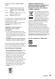
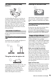
Notes on Installation and Usage Hot and humid Unsuitable Installation Do not install the projector in the following situations. Installation is these situations or locations may cause a malfunction or damage to the unit. Poorly ventilated locations • Avoid installing the unit in a location where the temperature or humidity is very high, or the temperature is very low. • To avoid moisture condensation, do not install the unit in a location where the temperature may rise rapidly.
Very dusty, extremely smoky locations Avoid installing the unit in a very dusty or extremely smoky environment. Otherwise, the air filter will become obstructed, and this may cause a malfunction of the unit or damage it. Dust preventing the air passing through the filter may cause a rise in the internal temperature of the unit. Clean the filter periodically. Unsuitable Conditions Do not use the projector under the following conditions.
B Overview Features High brightness, high picture quality High brightness Adopting Sony's unique optical system that provides a high-efficiency optical system. It allows the 165 W lamp to give a light output of 2000 ANSI lumen. High picture quality VPL-ES3: Three super-high-aperture 0.63inch SVGA panels with approximately 480,000 effective pixels, produce a resolution of 800 × 600 dots (horizontal/ vertical) for RGB input, and 500 horizontal TV lines for video input. VPL-EX3: Three super-high-aperture 0.
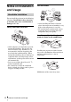
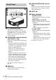
Location and Function of Controls f Front remote control detector g Lens Remove the lens cover before projection. Overview h Ventilation holes (exhaust) Top/Right Side/Front i Adjuster adjustment button 1 2 3 4 5 6 7 For details, see “Using the adjuster” on page 17. 8 j Adjuster k Connector Panel 9 0 For details, see “Connector Panel” on page 11. l Speaker m Adjusters (hind pad) n Lamp cover Rear/Bottom o Rear remote control detector qa qg Connects the supplied AC power cord.
d PUSH ENTER/v/V/b/B (Arrow) keys Control Panel 1 2 3 4 5 e INPUT key 6 a ?/1 (On/Standby) key Turns on the projector when the projector is in standby mode. The ON/ STANDBY indicator around the ?/1 key flashes in green until the projector is ready to operate. b ON/STANDBY indicator (located around the ?/1 key) Lights up or flashes under the following conditions: – Lights in red when the AC power cord is plugged into a wall outlet.
c OUTPUT connector Connector Panel 1 3 INPUT VIDEO AUDIO AUDIO INPUT A/B INPUT A INPUT B MONITOR REMOTE AUDIO RS232C 2 4 a VIDEO INPUT connector • S VIDEO (mini DIN 4-pin): Connects to the S video output (Y/C video output) of video equipment. • VIDEO (phono type): Connects to the composite video output of video equipment. • AUDIO jack (stereo minijack): To listen to sound output from video equipment, connect via this jack to the audio output of the video equipment.
c KEYSTONE (Trapezoidal distortion correction) key Adjusts the vertical trapezoidal distortion of the image. Pressing this key, the adjustment menu are displayed. Use the arrow keys (v/V/b/B) for adjustment. d RESET key Resets the value of an item to its factory preset value or returns the enlarged image to its original size. This key functions when the menu or a setting item is displayed on the screen. 2 Install the lithium battery. e PIC MUTING key Cuts off the picture.
B Projecting the Picture Installing the Projector The distance between the lens and the screen varies depending on the size of the screen. Use the following table as a guide. Screen Projecting the Picture Distance between the screen and the center of the lens Unit: m (feet) Screen size (inches) 40 80 100 150 200 250 300 Minimum Distance 1.2 (3.9) 2.3 (7.5) 2.9 (9.5) 4.4 (14.4) 5.9 (19.4) 7.3 (24) 8.8 (28.9) Maximum Distance 1.4 (4.6) 2.8 (9.2) 3.6 (11.8) 5.4 (17.7) 7.2 (23.6) 9.
Connecting the Projector To connect a computer Rear side When you connect the projector, make sure to: INPUT S VIDEO VIDEO AUDIO AUDIO INPUT A/B INPUT A INP • Turn off all equipment before making any connections. • Use the proper cables for each connection. • Insert the cable plugs firmly; loose connections may increase noise and reduce performance of picture signals. When pulling out a cable, be sure to pull it out by the plug, not the cable itself.
computer’s display and the external monitor, the picture of the external monitor may not appear properly. Set your computer to output the signal to only the external monitor. For details, refer to the operating instructions supplied with your computer. Note This section describes how to connect the projector to a VCR. For more information, refer to the instruction manuals of the equipment you are connecting.
To connect to a video GBR/ Component output connector Projecting Rear side INPUT S VIDEO VIDEO AUDIO AUDIO INPUT A/B INPUT A INP ON/STANDBY indicator to audio output (L) to audio output (R) to video GBR/ component output Rear remote control detector APA INPUT KEY STONE ENTER VCR Notes 16 Projecting MENU D ZOOM VOLUME PIC MUTING 1 Signal Cable (not supplied) HD D-sub 15-pin (male) ↔ 3 × phono jack 2 Stereo audio connecting cable (not supplied) (Use a no-resistance cable.
4 Press the INPUT key to select the input source.
8 Adjust the size of the picture and the focus. Adjust the picture size using the Zoom ring and adjust the picture focus using the Focus ring. Turning Off the Power 1 Press the ?/1 key. “POWER OFF? Please press ?/1 key again.” appears to confirm that you want to turn off the power. Note The message disappears if you press any key other than the ?/1 key, or if you do not press any key for five seconds. 2 Press the ?/1 key again.
B Convenient Functions Selecting the Menu Language You can select one of fifteen languages for displaying the menu and other on-screen displays. The factory setting is English. To change the menu language, proceed as follows: 4 Press the v or V key to select the MENU SETTING menu, then press the B or ENTER key. The selected menu appears. Front remote control detector 1 Plug the AC power cord into a wall outlet. 2 Press the ?/1 key to turn on the projector. 3 Press the MENU key. The menu appears.
Enter the password on this screen. Security Lock Enter new password key. The projector is equipped with a security lock function. When you turn the power of the projector on, you are required to input the previously set password. If you do not input the correct password, you will not be able to project the picture. Note You will not be able to use the projector if you forget your password and the password administrator is not available.
2 Enter the password. Enter the password that was set. Note If you call the customer service center because you have forgotten the password, you will need to be able to verify the projector’s serial number and your identity. (This process may differ in other countries/regions.) Once your identity has been confirmed, we will provide you with the password. Effective Tools for Your Presentation To enlarge the image (Digital Zoom function) You can select a section of the image to enlarge.
Use the arrow key (v/V/b/B) to scroll the enlarged image. To return the image to its original size Press the D ZOOM – key. Just pressing the RESET key returns the image back to its original size immediately. To freeze the image projected (Freeze function) Press the FREEZE key. “Freeze” appears when the key is pressed. This function works when a signal from a computer is input. To restore the original screen, press the FREEZE key again.
B Adjustments and Settings Using a Menu 3 Using a MENU Select an item. Use the v or V key to select the item, then press the B or ENTER key. The setting items are displayed in a popup menu or in a sub menu. The projector is equipped with an on-screen menu for making various adjustments and settings.
To clear the menu Press the MENU key. The menu disappears automatically if a key is not pressed for one minute. To reset items that have been adjusted Select the item that you want to reset, and then press the RESET key on the Remote Commander. “Complete!” appears on the screen and the setting of the item that you have selected is factory preset values.
The PICTURE SETTING Menu The PICTURE SETTING menu is used for adjusting the picture or volume. Items that can be adjusted or set depend on the kind of input signals. For details, see “Input signals and adjustable/setting items” on page 33. PICTURE SETTING Input A Picture Mode Adjust Picture... S t a n d a rd Vo l u m e : 30 PICTURE SETTING ADJUST PICTURE Contrast: Brightness: Gamma Mode: C o l o r Te m p .
The INPUT SETTING Menu The INPUT SETTING menu is used to adjust the input signal. Items that can be adjusted or set depend on the kind of input signals. For details, see “Input signals and adjustable/setting items” on page 33. When the video signal is input Setting items Functions Wide Mode Sets the aspect ratio of the picture. Off • Off: When a picture with a ratio of 4:3 is input. • On: When a picture with a ratio of 16:9 (squeezed) is input from a DVD player.
Setting items Shift Scan Converter Functions Initial setting Set according to Adjusts the position of the picture. H adjusts the horizontal position of the picture.V adjusts the vertical the input signal position of the picture. As the setting for H increases, the picture moves to the right, and as the setting decreases, the picture moves to the left. As the setting for V increases, the picture moves up, and as the setting decreases, the picture moves down.
The SET SETTING Menu The SET SETTING menu is used for changing the settings of the projector. SET SETTING S m a r t A PA : Auto Input Search: Input-A Signal Sel.: Color System: Pow e r S av i n g : IR Receiver: Pa n e l Key L o ck : Input-A On Off Component Au t o Off F ro n t & R e a r Off Setting items Functions Initial setting Smart APA The APA (Auto Pixel Alignment) automatically On adjusts “Dot Phase,” “H Size” and “Shift” on the INPUT SETTING menu for the input signal from a computer.
Setting items Functions Initial setting IR Receiver Selects the remote control detectors (IR Receiver) on the front and rear of the projector. • Front & Rear: Activates both the front and rear detectors. • Front: Activates the front detector only. • Rear: Activates the rear detector only. Front & Rear Panel Key Lock Locks all the control panel keys on the top panel of the Off projector so that the projector can be operated only with the Remote Commander. To lock the control panel keys, set to “On.
The MENU SETTING Menu The MENU SETTING menu is used for changing the menu displays. 30 Setting items Functions Initial setting Status (on-screen display) Sets up the on-screen display. When set to “Off,” turns off the on-screen displays except for the menus, a message when the power is turned off, and warning messages. On Language Selects the language used in the menu and on-screen displays.
The INSTALL SETTING Menu The INSTALL SETTING menu is used for changing the settings of the projector. INSTALL SETTING Input-A V Key s t o n e : 0 I m ag e F l i p : Off B a ck g ro u n d : Blue Lamp Mode: S t a n d a rd High Altitude Mode: O f f S e c u r i t y L o ck : Off Functions V Keystone Corrects the trapezoidal distortion caused by the projection 0 angle using the v/V/b/B keys on the Remote Commander. When the bottom of the trapezoid is longer than the top : Sets a lower value.
The INFORMATION Menu The INFORMATION menu displays the model name, serial number, the horizontal and vertical frequencies of the input signal and the cumulated hours of usage of the lamp. Model name INFORMATION VPL-ES3 fH: fV: Lamp Timer: Input A Serial No. 3 3 3 3 3 3 3 48,47kHz 60,00Hz No.23 1024x768 2 H Serial number Memory number of an input signal Signal type Setting items Functions fH Displays the horizontal frequency of the input signal. The displayed value is approximate.
Input signals and adjustable/setting items Adjust Picture... menu Item Input signal Video or S-Video (Y/C) Component Video GBR Computer B&W z z z z z Contrast z z z z z Brightness z z z z z Color z z z – – z – – – – z Picture Mode Adjust Picture... Hue (NTSC 3.58/4.43 only) Sharpness z z z – Gamma Mode – – z*1 z – Color Temp.
B Maintenance Note Replacing the Lamp The lamp used as a light source is consumable product. Thus replace the lamp with a new one in the following cases. • When the lamp has burnt out or dims • “Please replace the Lamp.” appears on the screen • The LAMP/COVER indicator lights up The lamp life varies depending on conditions of use. Use an LMP-C162 Projector Lamp as the replacement lamp. Use of any other lamps than the LMP-C162 may cause damage to the projector.
5 Insert the new lamp all the way in until it is securely in place (a). Tighten the two screws (b). Fold down the handle to replace it (c). Caution Do not put your hands into the lamp replacement slot, and do not allow any liquid or other objects into the slot to avoid electrical shock or fire. Disposal of the used lamp For the customers in the USA This product contains mercury. Disposal of this product may be regulated if sold in the United States.
Cleaning the Air Filter 3 Remove the air filter cover. 4 Remove the air filter. The air filter should be cleaned every 500 hours. Remove dust from the outside of the ventilation holes with a vacuum cleaner. 500 hours are approximate. This value varies depending on the environment or how the projector is used. Claws When it becomes difficult to remove the dust from the filter with a vacuum cleaner, remove the air filter and wash it. 1 Turn the power off and unplug the power cord.
B Others Troubleshooting If the projector appears to be operating erratically, try to diagnose and correct the problem using the following instructions. If the problem persists, consult with qualified Sony personnel. Power Symptom Cause and Remedy The power is not turned on. • The power has been turned off and on with the ?/1 key at a short interval. c Wait for about 45 seconds before turning on the power (see page 18). • The lamp cover is not secured. c Close the lamp cover securely (see page 35).
Symptom Cause and Remedy Color balance is incorrect. • The picture has not been adjusted properly. c Adjust the picture (see page 25). • The projector is set to the wrong color system. c Set “Color System” on the SET SETTING menu to match the color system being input (see page 28). The picture is too dark. • Contrast or brightness has not been adjusted properly. c Adjust the contrast or brightness on the “Adjust Picture...” menu properly (see page 25). • The lamp has burnt out or is dim.
Others Symptom Cause and Remedy The control panel keys do not function. The control panel keys are locked. c Unlock the control panel keys (see page 29). Indicators Symptom Cause and Remedy The LAMP/COVER indicator flashes. • The lamp cover or the air filter cover is detached. c Attach the cover securely (see pages 35 and 36). • The electrical system may have broken down. c Consult with qualified Sony personnel. The LAMP/COVER indicator lights up. • The lamp has reached the end of its life.
Caution Messages Use the list below to check the meaning of the messages displayed on the screen. Message Meaning and Remedy Not applicable! You have pressed the wrong key. c Press the appropriate key. The panel keys are locked! “Panel Key Lock” on the SET SETTING menu is set to “On.” c All the keys on the control panel of the projector are locked. Operate the projector with the keys on the Remote Commander (see page 29).
Specifications Optical characteristics 1) ANSI lumen is a measuring method of American National Standard IT 7.228. Electrical characteristics Color system NTSC3.58/PAL/SECAM/ NTSC4.43/PAL-M/PAL-N/ PAL60 system, switched automatically/manually (NTSC4.43 is the color system used when playing back a video recorded in NTSC on a NTSC4.43 system VCR.
INPUT B (VPL-EX3 only) HD D-sub15-pin (female) Analog RGB: R: 0.7 Vp-p ±2 dB (75 ohms terminated) G: 0.7 Vp-p ±2 dB (75 ohms terminated) G with sync/Y: 1 Vp-p ±2 dB sync negative (75 ohms terminated) B: 0.
5 6 7 8 GND GND (R) GND (G) GND (B) 13 14 15 HD/C.
Preset signals Memory Preset signal No. 15.734 59.940 Sync Video 60 Hz 2 Video 50 Hz 50 Hz 15.625 50.000 – 3 480/60i 480/60i 15.734 59.940 S on G/Y 4 575/50i 575/50i 15.625 50.000 S on G/Y 5 480/60p 480/60p (Progressive component 31.470 60.000 S on G/Y 6 575/50p 575/50p (Progressive component 31.250 50.000 S on G/Y 7 1080/60i 1035/60i, 1080/60i 33.750 60.000 S on G/Y 8 1080/50i 1080/50i 28.130 50.000 S on G/Y 10 720/60p 720/60p 45.000 60.
Memory Preset signal No. 45 1280 × 960 46 47 1280 × 1024 48 49* 50 1400 × 1050 fH (kHz) fV (Hz) Sync SXGA VESA 60 Hz 60.000 60.000 H-pos, V-pos SXGA VESA 75 Hz 75.000 75.000 H-pos, V-pos SXGA VESA 60 Hz 63.974 60.013 H-pos, V-pos SXGA VESA 75 Hz 79.976 75.025 H-pos, V-pos SXGA VESA 85 Hz 91.146 85.024 H-pos, V-pos SXGA+ 60 Hz 63.981 60.020 H-neg, V-neg Notes • When a signal other than the preset signals shown above is input, the picture may not be displayed properly.
Installation Diagram Floor Installation (Front Projection) Distance between the front of the cabinet and the center of the lens Front of the cabinet Wall Front of the lens 13.7 (9/16) Center of the screen Center of the lens Floor Unit: mm (inches) This section describes the examples of installing the projector on a desk, etc. See the chart on page 47 concerning the installation measurements. The alphabetical letters in the illustration indicate the distances below.
Unit: mm (inches) SS a b c 40 60 80 100 120 150 180 200 250 300 1190 1800 2400 3010 3620 4530 5440 6040 7560 9080 M 1370 N (46 7/8) (70 7/8) (94 1/2) (118 17/32) (142 5/8) (178 3/8) (214 1/4) (237 7/8) (297 3/4) (357 5/8) 2070 (81 5/8) 2760 3460 4160 5200 6240 6940 8680 10420 (54) x-203 x-305 x-406 x-508 x-610 x-914 x-1016 x-1270 x-1524 (x-16) (x-20) (x-24 1/8) x-762 (x-30) (x-36) (x-40) (x-50) (x-60) x-474 x-576 x-677 x-830 x-982 x-1084 x-
Ceiling Installation (Front Projection) Center of the screen 104.5 (4 1/8) Center of the lens 102.8 (41/8) 55 (2 1/4) Center of the Projector 83 (3 3/8) Holes for mounting a projector suspension support Ceiling Center of the lens Front of the cabinet Center of the screen Center of the lens 13.
Unit: mm (inches) SS 40 60 80 100 120 150 180 200 250 300 a’ N 1220 1820 2430 3040 3640 4550 5470 6070 7590 9110 M 1440 2090 2790 3490 5230 6270 6970 10450 (206) (247) (274 1/2) 8710 (109 7/8) (137 1/2) 4180 (82 3/8) b+362 b+463 b+565 b+819 b+971 b+1073 (48 1/8) (55 1/8) x b+260 (b+10 1/4) (71 3/4) (b+14 3/8) (95 3/4) (b+18 1/4) (119 3/4) (b+22 1/4) b (143 3/8) (179 1/4) (164 5/8) b+667 (b+26 3/8) (b+32 1/4) (215 1/2) (b+38 1/4) (239 1/8) (b+42
Dimensions Front 308 (12 1/4) 57 (2 1/4) 98 (3 7/8) 83 (3 3/8) Center of the lens Center of the projector Side 98 (3 7/8) 252 (10) 252 (10) Top 308 (12 1/4) Unit: mm (inches) 50 Dimensions
Index A Adjusting memory of the settings ........................24 the picture ............................................25 the picture size/shift .......................26, 27 Air filter ...................................................36 Auto Input Search ....................................28 B Background .............................................31 Batteries ...................................................12 Brightness ................................................25 C Color .............
S Scan Converter ........................................ 27 Screen size ........................................ 13, 41 Security Lock .................................... 20, 31 Sharpness ................................................ 25 Shift ......................................................... 27 Smart APA .............................................. 28 Specifications .......................................... 41 Status .......................................................
Sony Corporation