4-296-526-11 (1) Video Projector Operating Instructions VPL-VW95ES Sony Corporation Printed in Japan © 2011 Sony Corporation
WARNING To reduce the risk of fire or electric shock, do not expose this apparatus to rain or moisture. To avoid electrical shock, do not open the cabinet. Refer servicing to qualified personnel only. THIS APPARATUS MUST BE EARTHED. For the customers in the U.S.A. and Canada WARNING: Using this unit at a voltage other than 120 V may require the use of a different line cord or attachment plug, or both. To reduce the risk of fire or electric shock, refer servicing to qualified service personnel.
guarantee matters please refer to the addresses given in separate service or guarantee documents. AVERTISSEMENT Afin de réduire les risques d’incendie ou d’électrocution, ne pas exposer cet appareil à la pluie ou à l’humidité. werden. Überlassen Sie Wartungsarbeiten stets nur qualifiziertem Fachpersonal. DIESES GERÄT MUSS GEERDET WERDEN. CET APPAREIL DOIT ÊTRE RELIÉ À LA TERRE. Für Kunden in Europa Der Hersteller dieses Produkts ist Sony Corporation, 1-7-1 Konan, Minato-ku, Tokyo, 108-0075 Japan.
For the Customers in Brazil only DESCARTE DE PILHAS E BATERIAS Note on use of the USB charging AC power adaptor AC-UD10 For the customer in the U.S.A. The following FCC statement applies only to the version of this model manufactured for safe in the USA. Other versions may not comply with FCC technical regulations. Bateria Primária Atenção: Verifique as instruções de uso do aparelho certificando-se de que as polaridades (+) e (-) estão no sentido indicado.
Table of Contents Precautions .........................................7 Location of Controls Front/Right Side .................................8 Projecting Projecting the Picture on the Screen .............................................. 31 Rear/Bottom .......................................9 Turning Off the Power ............... 32 Using the Picture Position ............... 33 Remote Control ................................10 Selecting the Wide Screen Mode ....
Others About the Control for HDMI ........... 67 About the x.v.Color ......................... 68 About the simulated 3D feature ....... 68 Troubleshooting ............................... 69 Warning Indicators ..................... 72 Message Lists ............................. 73 Replacing the Lamp and the Air Filter and Cleaning the Ventilation Holes (intake) ............................................. 75 Cleaning the Air Filter ..................... 78 Cleaning and the Screen of the Projector .........
Precautions On safety • Check that the operating voltage of your unit is identical with the voltage of your local power supply. • Should any liquid or solid object fall into the cabinet, unplug the unit and have it checked by qualified personnel before operating it further. • Unplug the unit from the wall outlet if it is not to be used for several days. • To disconnect the cord, pull it out by the plug. Never pull the cord itself. • The wall outlet should be near the unit and easily accessible.
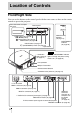
Location of Controls Front/Right Side You can use the buttons on the control panel with the same names as those on the remote control to operate the projector. Press the button and open the cover.
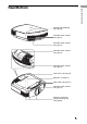
Location of Controls Rear/Bottom Remote control detector (1 page 20) Ventilation holes (intake) (1 page 14) Ventilation holes (intake) (1 page 14) Ventilation holes (intake) (1 page 14) Ventilation holes (intake) (1 page 14) Lamp cover (1 page 76) Adjusters (1 page 24) Filter holder (1 page 77) Ventilation holes (intake) (1 page 14) Projector suspension support attaching hole (1 page 89) 9
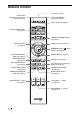
Remote Control Infrared transmitter LIGHT button Illuminates the buttons on the remote control.
Connections and Preparations Connections and Preparations This section describes how to install the projector and screen, how to connect the equipment from which you want to project the picture, etc.
VORSICHT Explosionsgefahr bei Verwendung falscher Batterien. Batterien nur durch den vom Hersteller empfohlenen oder einen gleichwertigen Typ ersetzen. Wenn Sie die Batterie entsorgen, müssen Sie die Gesetze der jeweiligen Region und des jeweiligen Landes befolgen. Installing batteries Two size AA (R6) batteries are supplied for Remote Control. To avoid risk of explosion, use size AA (R6) manganese or alkaline batteries. Caution about handling the remote control • Handle the remote control with care.
Step 1: Installing the Projector Installing the projector in such a location may cause a malfunction of the unit due to moisture condensation or rise in temperature. Near a heat or smoke sensor Before Setting Up the Projector Unsuitable installation Do not place the projector in the following situations, which may cause malfunction or damage to the projector. Malfunction of the sensor may occur.
Improper use Do not do any of the following while using the projector. Blocking the ventilation holes (intake or exhaust) Ventilation holes (intake) Ventilation holes (exhaust) Tip For details on the location of the ventilation holes (intake or exhaust), see “Location of Controls” on page 8. Tilting front/rear and left/right 15° or more 15° or more Avoid using the projector tilted at an angle of more than 15 degrees. Do not install the projector anywhere other than on a level surface or on the ceiling.
AVERTISSEMENT Connections and Preparations Lors de l’installation de l’appareil, incorporer un dispositif de coupure dans le câblage fixe ou brancher la fiche d’alimentation dans une prise murale facilement accessible proche de l’appareil. En cas de problème lors du fonctionnement de l’appareil, enclencher le dispositif de coupure d’alimentation ou débrancher la fiche d’alimentation.
Positioning the Projector and a Screen The installation distance between the projector and a screen varies depending on the size of the screen or whether or not you use the lens shift features. 1 Determine the installation position of the projector and screen. You can obtain a good quality picture if you position the projector so that the center of the lens is within the area indicated in gray in the illustration. Use the values L, x and y in the table on page 17 or 18 as a guide.
When using the 16:9 aspect ratio screen size Screen Size SS (inches) 40 60 80 100 120 150 200 250 300 1016 1524 2032 2540 3048 3810 5080 6350 7620 1201 1825 2448 3072 3695 4631 6189 7748 9307 (71 7/8) 2782 (96 1/2) 3723 (121) maximum (47 3/8) 1840 L x (72 1/2) 0 (145 1/2) (182 3/8) (243 3/4) (305 1/8) (366 1/2) 5605 7017 9371 11724 14077 4664 (109 5/8) (146 5/8) (183 5/8) (220 3/4) (276 3/8) 0 0 0 0 0 (369) 0 (461 5/8) (554 1/4) 0 0 (0) (0) (0) (0) (0) (0) (0)
When using the 4:3 aspect ratio screen size Screen Size SS (inches) 40 60 80 100 120 150 200 250 (mm) 1016 1524 2032 2540 3048 3810 5080 6350 7620 minimum 1480 2243 3006 3770 4533 5677 7585 9493 11401 (58 3/8) (88 3/8) 2262 (89 1/8) 3414 4566 5718 6870 8598 (134 1/2) (179 7/8) (225 1/8) (270 1/2) (338 5/8) L maximum x y x y x y 14357 17237 (565 1/4) (678 5/8) 0 0 0 0 0 0 0 0 (0) (0) (0) (0) (0) (0) (0) 396 (15 5/8) 594 (23 1/2) 81 792 (31 1/4) 991 (39 1/
2 Position the projector so that the lens is parallel to the screen. Top view Screen Project an image on the screen and adjust the picture so that it fits the screen (1 page 20). Note When using a screen with an uneven surface, stripes pattern may rarely appear on the screen depending on the distance between the screen and the projector or the zooming magnifications. This is not a malfunction of the projector.
Step 2: Adjusting the Picture Position Project an image on the screen and then adjust the picture position. 1 Remote control detector ON/STANDBY indicator 2 ?/1 (ON/ STANDBY) switch 3, 4, 5 POSITION button Tip (joystick) buttons on the side The ?/1 (ON/STANDBY), INPUT, MENU, and M/m/
Press the ?/1 (ON/STANDBY) switch to turn on the projector. The lens protector will open. The ON/STANDBY indicator flashes in green, and then lights in green. When the ON/STANDBY indicator flashes, “Starting...” appears on the screen. 3 Adjust the focus. Press the LENS ADJUSTMENT (FOCUS) button to display the Lens Focus adjustment window (test pattern). Then adjust the focus of the picture by pressing the M/m/
4 Adjust the picture size. Press the LENS ADJUSTMENT (ZOOM) button to display the Lens Zoom adjustment window (test pattern). Then adjust the size of the picture by pressing the M/m/
Note When adjusting the window position, do not touch the lens unit, otherwise your fingers may be pinched by the moving parts. Press
Note The range to move the picture projected on the screen can be adjusted only within the octagon area illustrated below. In this connection, see “Positioning the Projector and a Screen” (1 page 16) as well. Range of movement of the projected picture Projected Picture H: Width of the projected picture V: Height of the projected picture To adjust the tilt of the installation surface If the projector is installed on an uneven surface, use the adjusters to keep the projector level. Turn to adjust.
Step 3: Connecting the Projector Connecting to a VCR To connect to equipment with HDMI output connectors You can enjoy better picture quality by connecting a DVD player/recorder, Blu-ray Disc player/recorder, or PS3® equipped with HDMI output to the HDMI input of the projector. Moreover, if you have a Control for HDMI compatible equipment, you can operate the projector synchronizing with the Control for HDMI compatible equipment.
Notes • Use a high-speed HDMI cable. With a standard HDMI cable, images of 1080p, DeepColor, and 3D video images may not be displayed properly. • When connecting an HDMI cable to the projector, make sure the V mark on the upper part of the HDMI input of the projector and the v mark on the connector of the cable is set at the same position. • If the picture from equipment connected to the projector with an HDMI cable is not clear, check the settings of the connected equipment.
Connecting to a Computer Right side of the projector Connections and Preparations Computer to monitor output HD-Dsub15 pin cable (not supplied) or HDMI cable (not supplied) : Video signal flow When using an optional HDMI cable, be sure to use a Sony HDMI cable or other cable they has the HDMI logo. Tip When connecting an HD-Dsub15 pin cable, set “Input-A Signal Sel.” on the Setup menu to “Auto” or “Computer.” If the input signal does not appear properly, set it to “Computer” (1 pages 59, 73).
Connecting to an Optional TMR-PJ1 3D Sync Transmitter The projector incorporates a 3D Sync Transmitter. Depending on the installation environment of the projector, the 3D glasses may not received 3D signals properly from the projector’s built-in 3D Sync Transmitter. In this case, connect an optional TMR-PJ1 3D Sync Transmitter and place it near your viewing position. Right side of the projector TMR-PJ1 3D Sync Transmitter (not supplied) 2m (6.
Step 4: Selecting the Menu Language 2,3,4 M/m/
2 Press M/m to select the Setup menu, and press , or . The setting items of the selected menu appears. 3 Press M/m to select “Language,” and press , or . 4 Press M/m/
Projecting This section describes how to operate the projector to view the picture from the equipment connected to the projector. It also describes how to adjust the quality of the picture to suit your taste. Example: To view the picture from the video equipment connected to the HDMI 1 connector of this unit. 1 Power on both the projector and the equipment connected to the projector. 2 Press INPUT to display the input palette on the screen.
Notes on input of HDMI signal The projector adjusts the RGB dynamic range of the equipment connected with HDMI cable to the following to suit the HDMI standard and display in best picture quality. When video signal is input: Limited (16-235) When computer signal is input: Full (0-255) When a signal other than those of HDMI standard is input, the following symptoms may occur. • When a video signal is input, the color gradation of the dark area or bright area may become unclear, or texts may become faded.
Using the Picture Position 2 Press the M/m/ buttons to select the position. The lens position is automatically adjusted to the position that you select. Store or delete the Lens settings in the “Picture Position” of the Screen Menu (1 page 55). A position where a lens settings is not stored is displayed as “---.” Notes • After you have selected and confirmed the lens position, the lens starts to move automatically.
Selecting the Wide Screen Mode You can enjoy various wide screen modes according to the video signal received. Press WIDE MODE. Each time you press the button, you can select the “Wide Mode” setting. You can also select it using the menu (1 page 56). WIDE MODE button Original image When the Wide Mode is operated Wide Zoom (When a video signal is input) A 4:3 aspect ratio picture is enlarged naturally to fill the screen. The upper and lower portions of the screen are slightly cut off.
Letterbox picture with side panels Zoom Letterbox picture Anamorphic Zoom (When a video signal is input) When using an Anamorphic lens A 2.35:1 aspect ratio picture is converted to a normal 16:9 picture on the screen. This mode is best suited when using a commercially available Anamorphic lens which converts a normal 16:9 aspect ratio picture to a 2.35:1 picture.
• When a 3D video image is displayed, the “Wide Mode” setting is fixed at “Full.” Notes on selecting the wide screen mode The projector is featured with the WIDE MODE. When changing the settings of WIDE MODE, use caution as described below. • Select the wide screen mode taking into account that changing the aspect ratio of the original picture will provide a different look from that of the original image.
Watching 3D Video Images You can enjoy powerful 3D video images, such as from 3D games and 3D Blu-ray Discs, using the supplied the 3D glasses. Turn on the HDMI equipment for 3D compatibility connected to the projector then play the 3D content. For details on how to play 3D content, refer to the operating instructions for the connected equipment. 2 Turn on the projector and project the 3D video image onto the screen.
Using the Simulated 3D Function You can convert normal 2D video images to 3D video images. Tip For details on how to operate the on-screen menu, see “Operation through the Menus” (1 page 45). 1 Display the Function menu and select “3D Settings.” You can display the “3D settings” by pressing the 3D button on the remote control. 2 Set “2D-3D Display Sel.” to “3D,” and then press , to display “3D Format.” 3 Set “3D Format” to “Simulated 3D” (1 page 60). Tips • Use the supplied 3D glasses.
Using the 3D Glasses The 3D glasses receive signals the 3D Sync Transmitter built into the front of the projector and reflected to the glasses from the screen. When watching 3D video images using the 3D glasses, face squarely toward the screen. LED indicator 1 2 Projecting Power button Put on the 3D glasses. Press the power button on the 3D glasses. The LED indicator lights up in green. 3 Turn toward the screen.
Figure A: 3D glasses communication range (distance from the screen) Approx. 5 m (Maximum) 3D glasses Screen Top or side view Figure B:3D sync signal communication distance between the projector and screen Approx.
Selecting the Picture Viewing Mode You can select the picture viewing mode that best suits the type of program or room conditions. The availability of each picture mode depends on whether the video image is 2D or 3D. Projecting Press one of the PICTURE MODE buttons. DYNAMIC PICTURE MODE buttons Project bright images with sharp, vivid picture quality. STANDARD Ideal for projecting TV programs, sports, concerts, and other video images. CINEMA 1 Picture quality suited for watching movies.
Adjusting the Picture Quality You can easily adjust the picture quality that suits your taste by selecting the adjustment items with the remote control. The adjusted data can be stored in each picture mode. Selecting to Directly Adjust the Desired Menu Item MOTION ENHANCER button COLOR TEMP button COLOR SPACE button ADVANCED IRIS button BLACK LEVEL button GAMMA CORRECTION button 42 The following menu items can be adjusted by using the buttons on the remote control. “Motion Enhancer” “Color Temp.
Adjusting the Picture Using Real Color Processing Tip Freeze the scene of the video source when you are adjusting the picture using Real Color Processing. 2, 3, 4, 5 1 Press RCP on the remote control. 2 Press M/m to select “User 1,” “User 2” or “User 3,” then press ,. The RCP (Real Color Processing) window appears. 3 Select the target color you want to adjust. Repeat steps 1 and 2 described below to specify the target color.
2 Press M/m to select “Position” or “Range,” and specify it more delicate color position and color range you want to adjust using
Using the Menus This section describes how to make various adjustments and settings using the menus. Operation through the Menus RESET button 2, 3, 4 M/m/
1 Press MENU. The menu window appears. 2 Press M/m to select a menu item, and press , or . The items that can be set or adjusted with the selected menu appear. The item presently selected is shown in white.
3 Pop-up menu Press M/m to select an item you want to set or adjust and press , or . The setting items are displayed in a pop-up menu, in a setting menu, in an adjustment menu or in the next menu window.
4 Make the setting or adjustment of an item. To reset the items that have been adjusted When changing the adjustment level Select an item in the Menu screen, and display the pop-up menu, the setting menu, and the adjustment menu. Press the RESET on the remote control to reset only the selected settings to its factory preset value. To increase the value, press M/,. To decrease the value, press m/<. Press to restore the original menu screen. When changing the setting Press M/m to change the setting.
Picture Menu The Picture menu is used for adjusting the picture. Using the Menus Note These items may not be available, depending on the type of input signal. For details, see “Input Signals and Adjustable/Setting Items” (1 pages 85 to 88 ). Picture Mode You can select the picture viewing mode that best suits the type of picture or the environment. The availability of each picture mode depends on whether the video image is 2D or 3D. Dynamic: Project bright images with sharp, vivid picture quality.
Cinema Black Pro Advanced Iris Switches the iris function during projection. Auto 1: Automatically switches to an optimum iris according to a projected scene. The contrast of the scene is emphasized most. Auto 2: An optimum iris becomes smaller than when set to “Auto 1.” The contrast of the scene becomes reduced. Sensitivity: If “Auto 1” or “Auto 2” is selected, you can set the response speed that the iris is automatically switched according to a projected scene.
Adjusts the brightness of the picture. The higher the setting, the brighter the picture. The lower the setting, the darker the picture. You can make adjustments by pressing the BRIGHTNESS+/– on the remote control. Color Adjusts the color density. The higher the setting, the greater the intensity. The lower the setting, the lower the intensity. Hue Adjusts the color tone. The higher the setting, the more greenish the picture becomes. The lower the setting, the more reddish the picture becomes.
Expert Setting Film Mode According to the film source you have selected, make a setting for playback. Auto 1: Suited for reproducing a picture movement close to the original picture movement of the film source. Normally, set this to “Auto 1.” Auto 2: Reproduces a 2-3 or 2-2 Pull-Down format video signal, such as film sources, in a smooth picture movement. When a video signal other than 2-3 or 2-2 Pull-Down format is input, the picture is played back in progressive format.
Expert Setting Using the specified controller, “ImageDirector3” (supplied as a CDROM) allows you to adjust, set, and store a favorite tone in a computer. For detailed information on “ImageDirector3,” refer to the Help provided on the supplied CD-ROM in the computer. Note You can only perform adjustment with “ImageDirector3” when Gamma 1 to 6 are configured. Adjustment is not possible with Gamma 7 to 10 and Off. Color Space You can convert the range of color reproduction.
Advanced Picture Menu The Advanced Picture is used for adjusting the picture more. RCP (Real Color Processing) You can adjust the color, hue, and brightness of each selected portion of the picture independently. User 1, User 2, User 3: You can adjust the picture using Real Color Processing and store the settings. Once the settings are stored, you can view the picture with the adjusted picture quality. Off: Cancels this feature.
Screen Menu The Screen menu is used to adjust the input signal. You can adjust the size of the picture, and select wide screen mode, etc. . Using the Menus Note These items may not be available, depending on the type of input signal. For details, see “Input Signals and Adjustable/Setting Items” (1 pages 85 to 88). Picture Position You can store up to five lens settings. After selecting and confirming the desired position from among “Position 1” to “Position 5,” do “Save,” “Delete,” or “Select.
Wide Mode (Video signal) You can set the aspect ratio of the picture to be displayed for the current input signal (1 page 34). This item is enabled only when a video signal (preset memory numbers 3 to 14) (1 pages 83) is input. Wide Zoom: A 4:3 aspect ratio picture is enlarged naturally to fill the screen. The upper and lower portions of the screen are slightly cut off. Normal: A 4:3 aspect ratio picture is displayed in the center of the screen and enlarged to fill the screen vertically.
Reduces or enlarges the picture vertically. The screen is enlarged as the setting increases and reduced as the setting decreases. If the subtitle of a movie, etc. cannot be seen, use this together with “V Center.” Adjust Signal You can adjust the input signal. APA: Adjusts “Phase,” “Pitch,” and “Shift” automatically to a position that suits the image signal for pictures from a computer. Phase: Adjusts the dot phase and the phase of computer signal of pictures from a computer.
Setup Menu The Setup menu is used to change the factory preset settings, etc. Status Sets whether or not the on-screen display is displayed. Set to “Off” to turn off the on-screen displays except for certain menus, message when turning off the power, and warning messages. Language Selects the language used in the menu and on-screen displays.
Sets the power saving mode. When set to “On,” the projector goes into power saving mode if no signal is input for 10 minutes. At that time, the ON/STANDBY indicator lights in orange, then the screen becomes dark. In power saving mode, the power saving mode is cancelled if a signal is input or any button on the projector or the remote control is pressed. If you do not want to set the projector to power saving mode, select “Off.” Input-A Signal Sel.
Function Menu The Function menu is used for changing the settings of the various functions of the projector. 3D Settings You can change the settings of the 3D function. You can display the “3D settings” by pressing the 3D button on the remote control. 2D-3D Display Sel.: For Switching the video images to “2D” or “3D.” Auto: Displays 3D video images when HDMI signals with 3D information are input. Displays 2D video images when other signals are input.
3D Settings 3D Glasses Bri’ness: For adjusting the brightness of the picture when watching 3D video images using the 3D glasses. You can select the brightness from among “Min,” “1,” “2,” “3,” and “Max.” 3D Depth Adjust: For adjusting the depth of the 3D video images on the screen. The setting can be made only when a 3D Format other than “Simulated 3D” is selected. Notes • The menu display has a ghost while a 3D video image is displayed and is best viewed with the 3D glasses.
HDMI Setting Device List: Lists all the Control for HDMI compatible equipment connected to the projector. When “Enable” is selected, the Control for HDMI setting of Sony equipment (AV amplifier, video, etc.), which is compatible with “Control for HDMI - Easy Setting,” will also be effective.
Installation Menu The Installation menu is used for changing the installation settings. Using the Menus V Keystone Corrects the vertical trapezoidal distortion of the picture. When the bottom of the trapezoid is longer than the top ( Sets a lower value (– direction) When the top of the trapezoid is longer than the bottom ( Sets a higher value (+ direction).
IR Receiver Selects the remote control detectors (IR Receiver) on the front and rear of the projector. Front & Rear: Activates both the front and rear detectors. Front: Activates the front detector only. Rear: Activates the rear detector only. Blanking This feature allows you to adjust the displayable region within the four directions of the screen. Select the edge to adjust by highlighting Left, Right, Top, or Bottom using the M / m buttons. Adjust the amount of blanking using the < / , buttons.
Panel Alignment When “Zone” is selected: Select the position to adjust with < / , buttons for the horizontal position (H position) and M / m buttons for the vertical position (V position), then press . Set the amount to adjust with < / , buttons for the horizontal direction (H direction) and with M / m buttons for the vertical direction (V direction). You can select the position to adjust again by pressing . Reset: Returns to the factory settings.
Information Menu The Information menu displays the model name, serial number, the horizontal and vertical frequencies of the input signal and the cumulated hours of usage of the lamp. Model name: VPL-VW95ES Serial No. Memory No. Signal type Model name Displays the model name (VPL-VW95ES). Serial No. Displays the serial number. fH (horizontal frequency) Displays the horizontal frequency of the input signal. fV (vertical frequency) Displays the vertical frequency of the input signal. Memory No.
Others This section describes about the other functions, how to solve the problems, how to replace the lamp and air filter, etc. About the Control for HDMI Control for HDMI is an HDMI standard mutual control function which uses the HDMI CEC (Consumer Electronics Control) specification. By connecting a variety of Control for HDMI compatible equipment such as a hard disk Blu-ray Disc player, a DVD player/recorder, an AV amplifier, etc.
About the x.v.Color • “x.v.Color” is a promotion name given to the products that have the capability to realize a wide color space based on the xvYCC specifications and is a trademark of Sony Corporation. • xvYCC is an international standard of the technical specifications of the extendedgamut color space for video signals. The color gamut of xvYCC is wider than the one of sRGB that is used with the current television system.
Troubleshooting If the projector appears to be operating erratically, try to diagnose and correct the problem using the following instructions. If the problem persists, consult with qualified Sony personnel. Power Symptom The power is not turned on. Cause and Remedy Picture Symptom Cause and Remedy No picture. c Check that the proper connections have been made (1 page 25). c Select the input source correctly using the INPUT button (1 page 31).
Symptom Cause and Remedy The picture is not clear. c Adjust the focus (1 page 21). c Condensation has accumulated on the lens. Leave the projector for about 2 hours with the power on. The picture flickers. c For pictures from a computer, activate “APA” and adjust the current input signal. c Adjust “Phase” for “Adjust Signal” on the Screen menu properly (1 page 57). The color of characters or the picture is not appropriate.
3D video images Symptom The video image does not seem like 3D video images. Cause and Remedy c c c c c c c c Others Symptom Cause and Remedy The fan is noisy. c Check the setting of “Cooling Setting” on the Setup menu (1 page 58). c Make sure that the room temperature is not too high. c Check the installation conditions (1 page 13). The number of fan rotation increases to maintain the product reliability of the projector’s components in a room, where the temperature is higher than normal.
Warning Indicators The ON/STANDBY or LAMP/COVER indicator lights up or flashes if there is any trouble with your projector. LAMP/COVER indicator ON/STANDBY indicator Symptom Cause and Remedy LAMP/COVER flashes in red. (A repetition rate of 2 flashes) c Close the lamp cover securely, then tighten the screws securely (1 page 76). c Close the filter holder securely (1 page 77). LAMP/COVER flashes in red. (A repetition rate of 3 flashes) c The lamp has reached the end of its useful lifespan.
Symptom Cause and Remedy ON/STANDBY flashes in red. (A repetition rate of 5 times) c The lens protector is not fully open. Turn the power of the projector off and then on again. If the lens protector still does not fully open, consult with qualified Sony personnel. Tip In an urgent situation, refer to the illustration below to open the lens protector with your hands. Press the ?/1 (ON/STANDBY) switch to turn the power on and operate the projector.
Message Please clean the filter. Cause and Remedy c It is time to clean the air filter. Clean the air filter (1 page 78). Note To clear this message, press any button either on the remote control or the control panel of the projector once. Please clean the filter. Have you finished? Yes No c It is time to clean the air filter. Clean the air filter (1 page 78). c If you cleaned the air filter, select “Yes.” If you did not clean the air filter, select “No.” Projector temperature is high.
Replacing the Lamp and the Air Filter and Cleaning the Ventilation Holes (intake) 1 Turn off the projector and unplug the AC power cord. 2 When setting the projector on a flat surface such as a desk etc., put a cloth to prevent the surface from being scratched. Reverse the projector as illustrated, then place it on the cloth.
3 Loosen the screw on the lamp cover with a Philips screwdriver, and then open the lamp cover. 4 Loosen the 3 screws on the lamp with the Phillips screwdriver. Hold up the handle, then pull the lamp straight out. Note Be careful not to touch the optical block inside the unit. 6 5 76 Hold the handle of the new lamp and push it in securely until it reaches the end, and then tighten the 3 screws. Close the lamp cover, then tighten the screws.
7 Remove the filter holder. 8 Others Ventilation holes (intake) 12 Place the project back on its Remove the air filter. original position. 13 Turn on the projector, then select the desired setting item on the Setup menu. The menu screen below will be appeared. Claws 9 Attach the new air filter so that it fits into the each claws (10 positions) on the filter holder. 14 Select “Yes.” Note Attach the air filter aligning it with the shape of the filter holder.
• Be sure to turn off the projector and unplug the power cord before replacing the lamp, then check the ON/STANDBY indicator has already been turned off. • The projector will not turn on unless the lamp is securely installed in place. • The projector will not turn on unless the lamp cover are securely closed. • To cancel a message displayed on the screen, press either the button on the remote control or the one on the control panel on the projector. Note The lamp contains mercury.
Black points and bright points (red, blue, or green) on the screen The projector is manufactured using highprecision technology. You may, however, see tiny black points and/or bright points (red, blue, or green) that continuously appear on the projector. This is a normal result of the manufacturing process and does not indicate a malfunction. How to Use the USB Charging AC Power Adaptor Use the provided USB charging AC power adaptor to charge your 3D glasses.
3 Connect the USB cable to the USB connector of the supplied USB charging AC power adaptor. Supplied USB charging AC power adaptor 4 Connect the AC power cord for USB charging AC power adaptor to the supplied USB charging AC power adaptor. AC power cord for USB charging AC power adaptor 5 Plug the AC power cord for USB charging AC power adaptor into an AC outlet. Charging starts. The LED indicator on the 3D glasses lights up in orange while the glasses are being charged.
(75 ohms terminated) SYNC/HD: Composite sync input: TTL level, positive/ negative Horizontal sync input: TTL level, positive/negative VD: Vertical sync input: TTL level, positive/negative Specifications System Input/Output Y PB/CB PR/CR Component: phono type Y with Sync: 1 Vp-p±2 dB sync negative (75 ohms terminated) PB/CB: 0.7 Vp-p±2 dB (75 ohms terminated) PR/CR: 0.7 Vp-p±2 dB (75 ohms terminated) HDMI Digital RGB/Y CB (PB) CR (PR) INPUT A HD D-sub 15-pins Analog RGB/component: R/CR (PR): 0.
USB charging AC power adaptor (AC-UD10) (1) Specifications Input voltage: AC 100 to 240 V, 0.2 A, 50/60 Hz Rated output voltage: DC 5 V, 1.5 A Note Optional accessories Projector Lamp LMP-H202 (for replacement) Projector Suspension Support PSS-H10 3D glasses TDG-PJ1 3D Sync Transmitter TMR-PJ1 Please use the above power requirements. AC power cord for USB charging AC power adaptor (1) For the customers in the U.S.A.
Preset Signals The following table shows the signals and video formats which you can project using this unit. When a signal other than the preset signal shown below is input, the picture may not be displayed properly. Memory No. Preset signal (resolution) fH (kHz) fV (Hz) Sync H Size 480/60i 480/60i (720 × 480i) 15.734 59.940 SonG/Y or composite sync – 4 576/50i 576/50i (720 × 576i) 15.625 50.
Memory No. fH (kHz) fV (Hz) VESA 60 31.469 59.940 H-neg, V-neg 800 28 VESA 72 37.861 72.809 H-neg, V-neg 832 29 VESA 75 (IBM M3) 37.500 75.000 H-neg, V-neg 840 30 VESA 85 (IBM M4) 43.269 85.008 H-neg, V-neg 832 VESA 56 35.156 56.250 H-pos, V-pos 1024 32 VESA 60 37.879 60.317 H-pos, V-pos 1056 33 VESA 72 48.077 72.188 H-pos, V-pos 1040 34 VESA 75 (IBM M5) 46.875 75.000 H-pos, V-pos 1056 35 VESA 85 53.674 85.
Input Signals and Adjustable/Setting Items The items in the menus available to adjust differ depending on the input signal. The following tables indicate them. The items that cannot be adjusted are not displayed in the menu. Picture menu Item Input signal Video GBR signal Computer signal Advanced Iris z z z Lamp Control z z z Film Projection z z – Motion Enhancer z z – Contrast z z z Brightness z z z Color z z – Hue z z – Color Temp.
Screen menu Item Input signal Wide Mode Over Scan Screen Area * 2 V Center *4 Component signal Video GBR signal z z z *3 z z – z z (preset memory (preset memory numbers 7, 8, 9, 12, 13, numbers 7, 8, 9, 12, 13, 14 only) 14 only) Computer signal – z z z z z – APA – – z *5 Phase – – z *5 Pitch – – z *5 Shift z *5 z *5 z Vertical Size * 4 z : Adjustable/can be set – : Not adjustable/cannot be set *1: The setting can be made only when “x.v.Color” is set to “Off.
Compatible 3D Signals The projector accepts the following types of 3D signals. Resolution 720/60, 50P 3D signal format Side-by-Side format Over-Under format* Frame packing* Side-by-Side format* 1080/24P Over-Under format* 1080/60, 50P Side-by-Side format Others 1080/60, 50i Frame packing* Over-Under format *: Mandatory 3D format of the HDMI standards. 3D Signals and Adjustable/Setting Items Some items on the menus may not be available to adjust/set, depending on the 3D signals.
z: Adjustable/can be set –: Not Adjustable/cannot be set *1: The setting can be made for 2D display *2: The setting can be made for Over-Under format When the projector is set to convert 2D video images to 3D video images, some items on the menus may be not available to adjust/set, depending on the “3D Format” settings on the Function menu. The items that cannot be adjusted are not displayed on the menu. The following tables indicate these items.
Ceiling Installation Use the PSS-H10 Projector Suspension Support when you install the projector on a ceiling. The projection distances for ceiling installation are shown below.
When using the 16:9 aspect ratio screen size Screen Size SS (inches) 40 60 80 100 120 150 200 250 300 1016 1524 2032 2540 3048 3810 5080 6350 7620 1385 2008 2632 3256 3879 4814 6373 7932 9491 (54 17/32) (79 1/16) (103 5/8) (128 5/32) (152 23/32) (250 29/32) (312 9/32) (373 21/32) 2013 2955 3896 4837 5779 7190 9544 11897 14250 (79 9/32) (116 5/16) (153 3/8) (190 7/16) (227 1/2) (283 3/32) (375 3/4) (468 3/ (minimum) 249 (9 7/8) 374 (14 3/4) 498 (19 5/8)
Attaching the PSS-H10 projector suspension support For details on installation on a ceiling, refer to the Installation manual for Dealers of the PSS-H10. Make sure to consult with a qualified Sony personnel for installation. The installation measurements are shown below when installing the projector on a ceiling using the PSS-H10. Top view Install the projector so that the center of the lens is parallel to the center of the screen. 204.8 (8 1/16) 130 (5 1/8) Front of the cabinet Others 249.
Front view 150 (5 29/32) 75 (2 15/16) Ceiling 175 (6 7/8) The bottom surface of the mount bracket Center of the supporting pole 93.5 (3 11/16) Center of the lens 235 (9 1/4) 235 (9 1/4) 470 (18 1/2) Side view 204.8 (8 1/16) 130 (5 1/8) Front of the cabinet 249.8 (9 27/32) 235.1 (9 1/4) 484.
Index E Expert Setting ......................................... 51 Numerics F 3D Glasses 3D glasses communication range ........39 Using the 3D Glasses ...........................39 3D Settings 2D-3D Display Sel. .............................60 3D Depth Adjust ..................................61 3D Format ............................................60 3D Glasses Bri’ght ..............................61 Simulated 3D Effect ............................61 fH .............................................
O W Over Scan ................................................ 56 White Level Adj. .....................................52 WIDE MODE ..........................................34 Wide Mode Anamorphic Zoom ...............................56 Full .......................................................56 Full 1 ....................................................56 Full 2 ....................................................56 Normal .................................................56 Wide Zoom ...............