
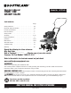
Use and Care Manual

ENG - 9Questions? Call Toll Free at 1-800-737-2112 Copyright © 2018 MAT Engine Technologies, LLC
Assembly Instructions (Continued)
B
Assembly (Continued)
• Save all instructions
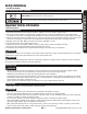
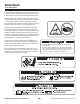
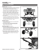
Install the tines (See Figure 3)
1. Slide the tines onto the tine axle. Install the internal tines
first. Sharp edge of the front and top tines should face
down and forward to till the ground. Insert the
M10 x 50 bolt with lock nut provided to secure the
inside tines. Use one flat washer under the head of the
bolt and one under the locknut. Tighten securely.
2. For wide 21” tilling, install the outside tines in the way
that the long half of the tine tube faces towards the
inside tines. For narrow 16” tilling, install the outside
tines in a way that the short half tine tube faces towards
the inside tines.
3. Insert the Lynch pins to secure the outside tines. Install
Lynch pins so the direction of the pin is from front-
to-back and the wire loop pivots over the top of the axle.
Secure by expanding the wire loop so it extends over
and captures the end of the pin. (Fig 3)
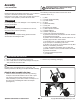
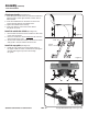
Install the drag bar
1. Insert the drag bar into the bottom of the wheel bracket
assembly. (See Figure 4)
2. Insert the pin through the bracket and the middle
hole of drag bar and secure with flat washer and
hairpin cotter. (See Figure 4B)
Install lower handle (See Figure 5)
1. Orient lower handle with upper square holes as shown.
Align lower handle holes with respective holes in the
frame and loosely install two M10 x 25 mm bolts, lock
washers and flat washers on each side.
2. Using a wrench, tighten bolts securely on each side.
3. Remove hairpin cotter and washer from clevis pin in
lower handle. Install link using the upper hole to clevis
pin and reinstall washer and hairpin cotter. Repeat
on opposite side.
Sharp edge of tine should face down to the ground.
Figure 4
Figure 4B
Figure 5
Figure 3