
SparkFun BabyBuck Regulator Breakout - 3.3V (AP63203) - Datasheet
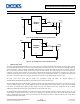
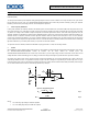

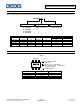
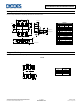
Table Of Contents

AP63200/AP63201/AP63203/AP63205
Application Information (continued)
Table 1 shows a list of recommended component selections for common output voltages for AP6300 and AP63201 referencing Figure 20.
AP63200/AP63201
Output Voltage (V)
R1 (kΩ)
R2 (kΩ)
L (µH)
C1 (µF)
C2 (µF)
C3 (nF)
C4 (pF)
1.2
30.9
62
2.2
10
2 x 22
100
100
1.5
54.2
62
2.2
10
2 x 22
100
100
1.8
77.5
62
3.3
10
2 x 22
100
100
2.5
131
62
3.3
10
2 x 22
100
100
3.3
182
62
6.8
10
2 x 22
100
100
5
157
30
10
10
2 x 22
100
100
12
249
18
10
10
2 x 22
100
56
Table 1. Recommended Component Selections for AP63200/AP63201
Tables 2 and 3 show recommended component selections for AP63203 and AP63205 referencing Figure 21.
AP63203
Output Voltage (V)
L (µH)
C1 (µF)
C2 (µF)
C3 (nF)
3.3
3.9
10
2 x 22
100
Table 2. Recommended Component Selections for AP63203
AP63205
Output Voltage (V)
L (µH)
C1 (µF)
C2 (µF)
C3 (nF)
5
4.7
10
2 x 22
100
Table 3. Recommended Component Selections for AP63205
10 Inductor
Calculating the inductor value is a critical factor in designing a buck converter. For most designs, the following equation can be used to calculate
the inductor value:
=
(
)
Eq. 7
Where ∆I
L
is the inductor ripple current, and f
SW
is the buck converter switching frequency. For AP63200/AP63201/AP63203/AP63205, choose ∆I
L
to be 30% to 50% of the maximum load current of 2A.
The inductor peak current is calculated by:
=
+
Eq. 8
Peak current determines the required saturation current rating, which influences the size of the inductor. Saturating the inductor decreases the
converter efficiency while increasing the temperatures of the inductor and the internal power MOSFETs. Therefore, choosing an inductor with the
appropriate saturation current rating is important. For most applications, it is recommended to select an inductor of approximately 2.2µH to 10µH
with a DC current rating of at least 35% higher than the maximum load current. For highest efficiency, the inductor’s DC resistance should be less
than 100mΩ. Use a larger inductance for improved efficiency under light load conditions.
11 Input Capacitor
The input capacitor reduces the surge current drawn from the input supply as well as the switching noise from the device. The input capacitor has
to sustain the ripple current produced during the on time of Q1. It must have a low ESR to minimize the losses.
The RMS current rating of the input capacitor is a critical parameter and must be higher than the RMS input current. As a rule of thumb, select an
input capacitor which has an RMS rating greater than half of the maximum load current.
Due to large dI/dt through the input capacitor, electrolytic, or ceramics with low ESR should be used. If a tantalum capacitor is used it must be
surge protected or else capacitor failure could occur. Using a ceramic capacitor greater than 10µF is sufficient for most applications.
AP63200/AP63201/AP63203/AP63205
Document number: DS41326 Rev. 2 - 2
13 of 18
www.diodes.com
January 2019
© Diodes Incorporated