SPECIALTY CONCEPTS Mark III/ 20 (SC3/ 20) Photovoltaic Battery Charge Controller Installation & Operation Manual SPECIALTY CONCEPTS, INC. 8954 Mason Ave. Chatsworth, Ca 91311 USA Copyright 5 / 1997 Specialty Concepts, Inc. GENERAL DESCRIPTION The Specialty Concepts Mark III/20 (SC3/20) is a battery charge controller and system monitoring unit designed for use in mobile or stationary photovoltaic (PV) energy systems.
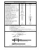
SPECIFICATIONS PARAMETERS UNITS Nominal Voltage (Volts) Short Circuit Current, Continuous (Amps) Short Circuit Current, Max (60 seconds) (Amps) Load Current, Continuous (1)(3) (Amps) Load Current, Max (60 seconds) (1)(3)(5) (Amps) Array Voltage, Max Voc (Volts) Operating Voltage @ Battery, Min. ( Charging) (Volts) Operating Voltage @ Battery, Min. ( LVD )(1) (Volts) Operating Voltage @ Battery, Min. ( Meter ) (Volts) Quiescent Current (Milliamps) Current Consumption, Charging, Typ.
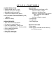
SC3/ 20 CHARGE REGULATION • 20 amp charge current, 12 volt • Switching shunt, pulse charging • Adjustable charging set-points • Temperature compensation (option) LOW VOLTAGE LOAD DISCONNECT (LVD) (option) • 10 amp LVD Relay DESIGN FEATURES • 100% solid state charge control • Designed for rugged mobile use • Over-current protection - Battery fuse • Reverse leakage protection - Blocking diode • Reverse polarity protection • Lightning protection • Input noise suppression • Low power consumption FEATURES MONIT
RELATED SYSTEM EQUIPMENT The SC3/20 is an integral part of a solar electric power system that includes a PV solar array, a battery and a load. These items should be installed in accordance with the National Electrical Code, and with the instructions provided by the equipment supplier.
INSTALLATION WARNINGS / CAUTIONS WARNING: Electricity, even low voltage electricity, can be dangerous. Installation should be performed by a licensed electrical contractor or other qualified personnel only. The requirements of the U.S. National Electrical Code should be followed. WARNING: Follow all safety precautions of the battery manufacturer. Proper ventilation must be provided for the batteries. Most batteries produce hydrogen gas when charging, which is extremely explosive.
INSTALLATION INSTRUCTIONS: 1. MOUNTING CONSIDERATIONS: - The SC3/20 is designed to be mounted flush against a wall. It can be mounted onto a wall by adding the optional knockout box (4x7 BOX). Flush mounting or wall mounting require different installation and mounting considerations. FLUSH MOUNT: The flush mounted unit requires a rectangular cut-out in the mounting surface with sufficient space (2-3 inches) immediately behind to accommodate the controller.
3. LOCATION: - The SC3/20 should be mounted where it can be easily seen and reached to take the best advantage of the metering. Carefully consider how the wires are to be run from the solar panel to the controller, and from the controller to the battery. The SC3/20 should be mounted as close to the battery as possible, and should be mounted on a vertical surface to aid in cooling.
9. RUN SYSTEM WIRING: - After disconnecting the power sources, run the wires from the battery and solar panel to the location selected for the controller. WALL MOUNT: Run the array and battery wires into the box through the knockouts, using a 1/2 inch Romex cable clamp for strain relief. 10. NOTE WIRE POLARITY: - Make sure to correctly mark the polarity of the wires using colored wires or tags. Incorrect polarity may blow the front panel fuse or damage the SC3/20.
15. INSTALL FUSING AS NEEDED: - Add circuit protection where needed. A 20 amp fuse and disconnect switch should be installed on the Battery (+) run of the SC3/20. 16. RECONNECT BATTERY AND ARRAY POWER 17. CHARGE SET-POINT ADJUSTMENT (RE-CALIBRATION) TO NON-STANDARD SETPOINTS: - Usually not needed. It is recommended that any adjustment be done by users with electronic experience. Incorrect settings can lead to the over-charge or undercharge of batteries or damage to the SC3/20.
FIGURE 1 SC3/20 CHARGE CONTROLLER SOLAR PANEL ARRAY + Yellow (+) ← + Green (-) LOAD Black (-) Red (+) A B + Temp.Sensor (Optional) BATTERY FIGURE 2 FUSE RATINGS: A = 20 Amp / Disconnect switch B = Rated for load SC3/20 with E-OPTION (LVD) SOLAR PANEL ARRAY + Yellow (+) Green (-) ← + Black (-) Red (+) LOAD A White White C + Temp.Sensor (Optional) BATTERY FUSE RATINGS: A = 20 Amp/ Disconnect switch C = Rated for load, up to 10 amps max.
FIGURE 3 SC3/20 using External Shunt SOLAR PANEL ARRAY + DC LOAD (OR) INVERTER / CHARGER (OR) Yellow (+) GENERATOR / ALTERNATOR Green (-) ← Blue Brown + Blue wire nut Blue wire nut Black (-) Red (+) A D + BATTERY EXTERNAL SHUNT (negative leg) FUSE RATINGS: A = 20 Amp / Disconnect switch D = Rated for load, inverter or charging source FIGURE 4 SC3/20 BACK VIEW Decimal Point Programming Pin Jumper : Remove jumper when using 500 amp / 50 mv external shunt.
OPERATION The charge regulation aspects of the SC3/20 are completely automatic. No user interface is required after installation. This controller will regulate the charging of batteries during conditions of heavy usage, or when left unattended for long periods of time. SWITCHING SHUNT, PULSE CHARGE REGULATION: When in the charge mode, the SC3/20 allows maximum available array current to flow into the battery through a blocking diode, lighting the yellow "CHARGING" light.
CHARGE SET-POINT ADJUSTMENT CHARGE SET-POINT ADJUSTMENT SHOULD BE ATTEMPTED ONLY BY QUALIFIED PERSONNEL. IMPROPER CALIBRATION CAN RESULT IN BATTERY AND EQUIPMENT DAMAGE. The standard charging set-points of the SC3/20 will be proper for a majority of the applications, however the SC3/20 allows field adjustment of charging set-points. Caution should be used, and calibration should not be attempted if there is any doubt about the procedure or ultimate set-points required.
MONITORING The system operation can be monitored by using the digital meter and the lights on the front of the controller. DIGITAL DISPLAY: The Digital display on the front of the SC3/20 provides metering of four parameters, selected by a four position slide switch to the right of the display, labeled A, B, C and D. POSITION A - "BATTERY VOLTAGE": This displays the system battery voltage. The battery voltage is a general indication of battery condition, or capacity.
“CHARGED” LIGHT: The "CHARGED" light will be on when the array is active and the battery has already reached the charge termination voltage. It will go out when the battery drops below the charge resume voltage. Systems with high charge rate (more than 1 panel per battery), or with old batteries may see the “CHARGED” light on sooner or more often. In this case batteries may not be fully charged, but the controller is preventing overcharging by switching off for a brief period.
OPTIONS The following are instructions for installing and using the options that are available on the SC3/20. These options must be specified at the time of an order; options can not be added to finished units. OPTION A - Temperature Compensation: DESCRIPTION: On units equipped with temperature compensation, a small sensor on a ten foot cable is wired into the controller to adjust the charging thresholds according to battery temperature.
TROUBLE SHOOTING The following section can assist in the troubleshooting of a solar system. Please review the section below titled “HELP NOTES” which lists some common problems with a solar system. If a possible problem with the SC3/20 is suspected based on the observations and notes in the “MONITORING” section, refer to the chart titled SC3/20 PROBLEMS and the case note for each condition.
8. BAD CONNECTION: PANEL - This may include problems with the connections to the SC3/20 (yellow wire and green wire), at either array terminals (“+” or “-”) or in fuses and crimp connectors in these lines. 9. BAD CONNECTION: BATTERY - This may include a blown fuse at the front of the SC3/20 (See CONTROLLER FUSE BLOWN below). A bad battery connection could also be caused be a defective fuse, a bad fuse holder or problems with the connections in the system.
SC3/20 PROBLEMS: - Refer to this chart and the SC3/20 PROBLEM CASES (next page) to help diagnose potential problems based on the SC3/20 readings. CASE BATTERY VOLTAGE READING ARRAY CURRENT READING YELLOW CHARGING LIGHT GREEN CHARGED LIGHT #1 → Display blank Display blank OFF OFF #2→ Display blank Display blank OFF OFF #3 → 10-13 00.0 OFF #4 → 12.0-14.7 00.0 ON #5 → 13-14.7 00.0 ON #6 → 14.7 - 22.
SC3/20 PROBLEM CASES (from SC3/20 PROBLEMS chart) SC3/20 Case 1 - Check the battery voltage. Minimum operating voltage for the display is about 10 volts. If the battery voltage is over 10 volts then this condition indicates that a bad connection exists to both the battery (See BAD CONNECTION: BATTERY (Help Note #9)) and the solar panel (See BAD CONNECTION: PANEL (Help Note #8)) or that the SC3/20 is defective.
SC3/20 Case 16 - The reading of the charge termination set-point (Position “C”) will differ at warm or cool times. The actual voltage set-point remains unchanged. Monitor and adjust the set-point at times of mild ( or “room temperature”). BATTERY PROBLEMS: - Refer to this section to help diagnose potential problems based on battery observations.
SOLAR PANEL PROBLEMS: CASE PANELS 1 → Less charge than expected - Refer to this section to help diagnose potential problems based on panel performance. SEE NOTE(S) See Panel note 1 Panel Note 1 - The panels should generate a charge close to their rated short circuit current as presented in their specifications. To reach this level assumes that all conditions are ideal.
LIMITED FIVE YEAR WARRANTY SPECIALTY CONCEPTS, INC. 1. Specialty Concepts, Inc. warrants all its products for a period of five (5) years from the date of shipment from its factory. This warranty is valid against defects in materials and workmanship for the five (5) year warranty period. It is not valid against defects resulting from, but not limited to: A. Misuse and/or abuse, neglect or accident. B. Exceeding the unit's design limits. C.