
Instruction Manual


WIRING DIAGRAM NOTES
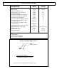
FUSE RECOMMENDATIONS
Location A: Should be rated for the lesser of the array, load and wire.
Location B: 5 - 10 amp fuse.
Location C: 1 amp fuse
=============================================================================
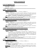
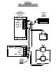
FIGURE 1 - Timer with ASC Controller
TIMER TERMINAL CONNECTIONS
Batt / Array (-): To ASC BATT (-). (...or to Array (-) or Battery (-) )
Load (-): To load (-).
Array (+): To ASC ARRAY (+): The wire from the SCT ARRAY (+) terminal does not carry any
current, therefore, small gauge wire may be used. (Wire as shown in diagram; this
connection MUST be made to the array side of the system's blocking diode.)
Batt / Load (+): To ASC BATT (+) and additional wire connected to load (+)
LOAD May be a relay coil to increase load current capability of Timer. Negative side of load is
controlled. Do not connect Load (-) to system common.
=============================================================================
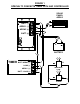
FIGURE 2 - Timer with ASC Controller with Low-Voltage Load Disconnect (LVD)
TIMER TERMINAL CONNECTIONS
Batt / Array (-): To ASC BATT (-) (...or to Array (-) or Battery (-) )
Load (-): To load (-)
Array (+): To ASC ARRAY (+): The wire from the SCT ARRAY (+) terminal does not carry any
current, therefore, small gauge wire may be used. (Wire as shown in diagram; this
connection MUST be made to the array side of the system's blocking diode.)
Batt / Load (+): To ASC BATT (+)
LOAD May be a relay coil to increase load current capability of Timer. Negative side of load is
controlled. Do not connect Load (-) to system common.
=============================================================================
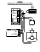
FIGURE 3 - Timer with Charge Controller with LVD (Non-ASC Controller)
TIMER TERMINAL CONNECTIONS
Batt / Array (-): To Controller Batt (-) (...or to Array (-) or Battery (-) )
Load (-): To load (-)
Array (+): If controller has blocking diode, this connection goes to Controller Array (+). If
controller does not have a blocking diode, install one as shown and wire this connection
to array side of blocking diode. The wire from the SCT ARRAY (+) terminal does not
carry any current, therefore, small gauge wire may be used. This connection MUST be
made to the array side of the system's blocking diode.
Batt / Load (+): To Controller Batt (+)
LOAD May be a relay coil to increase load current capability of Timer. Negative side of load is
controlled. Do not connect Load (-) to system common.
=============================================================================
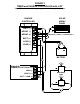
FIGURE 4 - Timer with Photo sensor
TIMER TERMINAL CONNECTIONS
Batt / Array (-): To Controller Batt (-) (...or to Array (-) or Battery (-) )
Load (-): To load (-)
Array (+): To Photo sensor (either wire).
Batt / Load (+): To Controller Batt (+) (or Battery (+) ), and a second wire to load (+) and a
third wire to the photo sensor
CONTROLLER No controller or blocking diode is needed for the operation of the timer and load.
LOAD May be a relay coil to increase load current capability of Timer. Negative side of load is
controlled. Do not connect Load (-) to system common.