Link 150 M3 MCU Installation and Operation Link Wireless Telephone System Part Number: 72-0075-01 Issue F
SpectraLink Corporation Installation and Operation Link WTS – Link 150 M3 MCU Notice SpectraLink Corporation has prepared this document for use by SpectraLink personnel and customers. The drawings and specifications contained herein are the property of SpectraLink and shall be neither reproduced in whole or in part without the prior written approval of SpectraLink, nor be implied to grant any license to make, use, or sell equipment manufactured in accordance herewith.
SpectraLink Corporation Installation and Operation Link WTS – Link 150 M3 MCU WARNING: Changes or modifications to this equipment not approved by SpectraLink Corporation may cause this equipment to not comply with part 15 of the FCC rules and void the user’s authority to operate this equipment. WARNING: SpectraLink products contain no user-serviceable parts inside. Refer servicing to qualified service personnel.
SpectraLink Corporation Installation and Operation Link WTS – Link 150 M3 MCU Table of Contents 1. About This Document 1.1 1.2 1.3 1.4 SpectraLink Corporation Model Numbers Related Documents Customer Support Hotline Icons and Conventions 2. Installation Overview 2.1 Installation Steps and Responsibilities 3. Link Wireless Telephone System Overview 3.1 3.2 System Operation The Front Panel of the Link 150 M3 MCU 4. Site Preparation 4.1 4.2 Required Materials Determine Location of MCU 5.
SpectraLink Corporation 12. Technical Parameters 12.1 12.2 Select Alternate Spread Spectrum Sequence Change Companding PN: 72-0075-01-F.
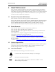
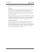
SpectraLink Corporation 1. Installation and Operation Link WTS – Link 150 M3 MCU About This Document This document explains installation and operation of SpectraLink’s Link Wireless Telephone System (Link WTS), using the Link 150 Model 3 (M3) Master Control Unit (MCU). The Link 150 M3 MCU adds wireless service to your existing telephone system. The installation process connects the Link WTS to your telephone system, and activates the Link Wireless Telephones. 1.
SpectraLink Corporation 2. Installation and Operation Link WTS – Link 150 M3 MCU Installation Overview Installation has three phases. In most cases, a separate person is responsible for each phase. 1. Site preparation and wire installation: This is usually done by a wire technician or contractor. 2. Installing the SpectraLink system: This is done by SpectraLink or one of our certified distributors. 3.
SpectraLink Corporation 2.
SpectraLink Corporation 3. Installation and Operation Link WTS – Link 150 M3 MCU Link Wireless Telephone System Overview Review this section if you are unfamiliar with the features and operation of the Link WTS. 3.1 System Operation The Link WTS is a wireless communication system that offers direct telephone access for incoming and outgoing calls anywhere within a facility.
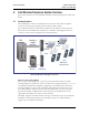
SpectraLink Corporation Installation and Operation Link WTS – Link 150 M3 MCU SpectraLink offers an analog MCU that works with telephone systems (CO, PBX or Key Systems) with analog (loop start) ports. We also offer digital MCUs that work with the most common brands of telephone systems’ (PBX or key systems) digital ports. Base Stations Act as a radio transceiver to provide the communications signal between the handset and the MCU.
SpectraLink Corporation 3.2 Installation and Operation Link WTS – Link 150 M3 MCU The Front Panel of the Link 150 M3 MCU The MCU’s front panel contains the connections to the telephone system, switches to control system administration, and status LEDs. 1. STEP Button: Selects a specific line or Base Station during registration process. 2. Mode Switch: Selects the mode of operation for the Link 150 M3 MCU.
SpectraLink Corporation Installation and Operation Link WTS – Link 150 M3 MCU 4. Site Preparation 4.1 Required Materials The following equipment must be provided by the customer: Outlet Strip Recommended for installations with more than one MCU. This will allow the MCUs to be turned on and off together. Cross-Connect Block Required to connect the telephone switch ports and the Base Stations to the MCU. 25 Pair Cables RJ-21 male at MCU end, required to connect the MCU to the cross-connect blocks.
SpectraLink Corporation Installation and Operation Link WTS – Link 150 M3 MCU 5. Run Cable for System 5.1 Run Cables to Base Station Locations The Base Station locations should be designated on the building floor plans provided to the SpectraLink field service engineer. Base Stations can be mounted easily on raised or acoustical ceiling tiles, or on the wall. Avoid locating Base Stations in high or hard-to-reach places, as this will hinder maintenance, testing and/or repositioning.
SpectraLink Corporation Installation and Operation Link WTS – Link 150 M3 MCU When cabling an external Base Station or a Base Station with wiring that exits the building, protect all Base Station wiring with the Quick Clip Fuse (Illinois Tool Works, Linx Division, SCP-2X2) before bridging with other Base Station power leads. Run all cable before attaching the RJ-45 connectors to the Base Stations.
SpectraLink Corporation Installation and Operation Link WTS – Link 150 M3 MCU When wiring the 8-pin connector, use the following table as a guide. 8-pin Modular Connector 5.4 MCU Pin Function Polarity 1 Data 1 Any 2 Data 2 Any 3 Power 3 + 4 Power 2 - 5 Power 2 + 6 Power 3 - 7 Power 1 - 8 Power 1 + Prepare Demarc Blocks The MCU connects to the existing telephone system using RJ-21 connections.
SpectraLink Corporation Installation and Operation Link WTS – Link 150 M3 MCU Multiple Power Pairs Some sites may prefer to wire Base Stations to a separate demarc block in order to split out power pairs. Dedicated Line for Diagnostic Modem The Link 150 M3 MCU can be accessed remotely using an internal modem. To use the modem for remote access, a dedicated dial-in line must be provided. On digital interface systems this line must be terminated as a digital extension to the MCU.
SpectraLink Corporation Installation and Operation Link WTS – Link 150 M3 MCU Four-wire Digital Interface The wiring diagram below shows the connections required for a four-wire interface . Each MCU of this type requires two demarcation blocks which will be wired as indicated. B A Receive (RX) To PBX Telephone Ports Pair 1-16 Pair 17-25 Unused To PBX Transmit (TX) From PBX Telephone Ports Pair 1-16 Pair 17 - Unused Power Pairs 18-19 To Base Stations Base Stn. 1-4 Data Pairs 20-23 Base Stn.
SpectraLink Corporation 5.5 Installation and Operation Link WTS – Link 150 M3 MCU Install Demarc Blocks The demarcation blocks used to connect the telephone system and Base Stations to the MCU should be installed on a typical telephone facility backboard. A 1/2” or 3/4” thick board mounted on the wall near the MCU is typical. Although this manual uses 66 blocks as examples, any standard cross-connect blocks are acceptable.
SpectraLink Corporation 5.7 Installation and Operation Link WTS – Link 150 M3 MCU Connect Cables from Base Stations and Phone Lines to Demarc Blocks Two-pair twisted cable from Base Stations installed throughout the facility converge at the demarc block or backboard. Each MCU can support four Base Stations and up to 16 handsets. The Base Station and Link Wireless Telephone cables are punched down onto the demarc/cross-connect blocks as shown in the demarc block diagrams below.
SpectraLink Corporation Installation and Operation Link WTS – Link 150 M3 MCU Two-wire Analog or Digital Demarc Block The demarc block for the two-wire analog or digital interface should be wired as follows.
SpectraLink Corporation Installation and Operation Link WTS – Link 150 M3 MCU Four-wire Digital Demarc Block The four-wire digital interface (future release) requires two demarc blocks, one to Connector A and one to Connector B on the MCU. They should be wired as follows.
SpectraLink Corporation Installation and Operation Link WTS – Link 150 M3 MCU Line 1 RX Line 2 RX Line 3 RX Line 4 RX Line 5 RX Line 6 RX Line 7 RX Telephone Ports Note: RX denotes data received by the telephone system from Link 150 Line 8 RX Line 9 RX Line 10 RX Line 11 RX Line 12 RX Line 13 RX Line 14 RX Line 15 RX Line 16 RX tip ring tip ring tip ring tip ring tip ring tip ring tip ring tip ring tip ring tip ring tip ring tip ring tip ring tip ring tip ring tip ring 25 PAIR MALE CONNECTOR CABLE TO
SpectraLink Corporation Installation and Operation Link WTS – Link 150 M3 MCU 6. Install Link Wireless Telephone System 6.1 Survey Site Check the site to be sure pre-installation work has been completed correctly. This includes: • Location chosen for the MCU is adequate, and power is available. • Wiring to Base Station locations has been pulled and correctly terminated. • Phone lines for the Link Wireless Telephones are installed and properly terminated.
SpectraLink Corporation Installation and Operation Link WTS – Link 150 M3 MCU ESD Bonding Straps To provide static protection for the MCU. Link Wireless Telephones The correct number of handsets for this installation. Battery Chargers Link Wireless Telephones require a Battery Charging system, usually one per handset. Battery Packs The system may have one or more spare Battery Pack per handset, depending on the needs at your location.
SpectraLink Corporation Installation and Operation Link WTS – Link 150 M3 MCU Connect Multi-Unit Systems Use the following procedure to connect multiple MCUs. 1. Mount the MCUs side by side. 5555 2. Connect the IPC cable from the OUT port of the first unit to the IN port of the adjacent unit. Repeat until all units are connected, as shown in the following illustration.
SpectraLink Corporation Installation and Operation Link WTS – Link 150 M3 MCU Connect Power 1. Connect the power plug from the AC adapter to the jack labeled PWR on the MCU. Use only the provided Class II AC Adapter with output 24VDC, 1A. For installations with more than one MCU, use an outlet strip with a built-in power switch. This allows the MCUs to be turned on and off together. 2. Plug the AC adapter into a 110VAC outlet or switch on the outlet strip to apply power to the MCU.
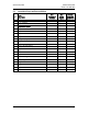
SpectraLink Corporation Switch Interface Installation and Operation Link WTS – Link 150 M3 MCU Line LEDs MCU Type Analog 1 SCA5xx Comdial 3 SCU5xx DEFINITY – Two-wire 1, 4 SCU5xx DEFINITY – Four-wire 1, 5 SCF5xx Four-wire Interface. Executone 2, 5 SCB5xx The SCB will only support Executone. Fujitsu 2, 4 SCU5xx Inter-Tel 2, 3, 4 SCU5xx Meridian 1, 2 SCU5xx Merlin Legend 1, 3 SCF5xx Four-wire Interface. Mitel 1, 2, 3 SCX5xx The SCX will only support Mitel.
SpectraLink Corporation 6.4 Installation and Operation Link WTS – Link 150 M3 MCU Install Base Stations Be sure the Base Station is positioned clear of anything that might damage it. The Base Station should be well above head height, away from doors and other objects that might strike it, and away from areas open to the elements or possible water leaks. Check your location for other radio antenna devices and place the Base Stations to avoid interference.
SpectraLink Corporation Installation and Operation Link WTS – Link 150 M3 MCU Mount Base Stations On Finished Ceilings If your site does not have a dropped tile ceiling, the Base Station can be mounted to a finished ceiling or wall with a 4 to 5” long 1/4” –20 TPI plastic or nylon screw or bolt (such as a lag screw). The customer’s wire contractor is responsible for this installation. 1. Drill two holes approximately 1” apart.
SpectraLink Corporation 6.5 Installation and Operation Link WTS – Link 150 M3 MCU Install Outdoor Base Stations Outdoor Base Stations are equipped with a protective enclosure, designed to be mounted to a wall or pole. After the enclosure is mounted, the Base Station is inserted in the enclosure and connected. Only RCO Base Stations can be used outdoors. The customer’s wire contractor is responsible for wiring and mounting the outdoor Base Station enclosure.
SpectraLink Corporation Installation and Operation Link WTS – Link 150 M3 MCU 7. Connect and Register Handsets 7.1 Set Up Diagnostic Modem Each MCU has an internal modem feature that allows SpectraLink technicians to dial into the system for troubleshooting and maintenance. The modem is enabled on Line 1 when no handset is registered to Line 1. When enabled, the modem will autoanswer an incoming call to that line. This internal modem uses proprietary communication software.
SpectraLink Corporation Installation and Operation Link WTS – Link 150 M3 MCU The LINE indicator LEDs now show the registration status of each line. • If the LED is on, a handset is registered to the line. • If the LED is off, no handset is registered to the line. 3. Press the STEP button until the LED for the line to be registered flashes. • If the LED is flashing, that line is selected.
SpectraLink Corporation 7.5 Installation and Operation Link WTS – Link 150 M3 MCU • If the Link 150 M3 MCU is connected to your telephone system via analog lines, refer to the for analog systems. • If your Link 150 M3 MCU is connected to a digital key telephone system or PBX, refer to the document that deals specifically with your brand of telephone system. Test Handsets Verify proper registration and operation of each handset by performing the following steps. 1. Press the START key on each handset.
SpectraLink Corporation 8. Installation and Operation Link WTS – Link 150 M3 MCU Site Certification The SpectraLink field service engineer should not leave the site before contacting SpectraLink to perform remote install verification. Contact a SpectraLink engineer on the Customer Support Hotline at (800) 775-5330. The hours of operation are 6 a.m. to 6 p.m. Mountain time, Monday through Friday.
SpectraLink Corporation Installation and Operation Link WTS – Link 150 M3 MCU 9. System Administration 9.1 Troubleshoot Error Codes When an alarm is detected, the ERROR LED will light and the MCU’s STATUS LEDs will display an alarm code. If the error code refers to a Base Station problem, the Base Stn LED will indicate which Base Station has the problem. If more than one Base Stn LED is on, the error code refers to the lowest numbered Base Station with an error.
SpectraLink Corporation 9.3 Installation and Operation Link WTS – Link 150 M3 MCU Status LED Codes STATUS LEDs 12345 Description Action Random Cycling The Link 150 M3 MCU is powering up. Initialization to follow. This is not an error and should change to another code after a minute. 5 Link 150 M3 MCU is initalizing. Code number will change when finished. 1, 2, 3, or 4 MCU identification number. Indicates normal operation when it is on steady.
SpectraLink Corporation STATUS LEDs Installation and Operation Link WTS – Link 150 M3 MCU Description Action 4, 5 The switch type selected is not supported by this MCU. Verify that the switch type selected is correct. If the type is incorrect, repeat the steps to select a new switch type. See section 6.3 Install MCUs -Set Switch Interface Type 1, 4 The operator is trying to register a handset or place an admin call on an MCU with no phone lines. Return mode switch to the NORMAL position.
SpectraLink Corporation Installation and Operation Link WTS – Link 150 M3 MCU Handset Status Indicator Messages Indicator Description Action BATT Displays when user is on the handset and the battery charge is low. The user has two minutes to complete the call. Replace the Battery Pack with one that is charged. BATTERY LOW Displays when user is not on the handset and battery charge is low. The handset will ring to alert user to this condition.
SpectraLink Corporation 9.4 Installation and Operation Link WTS – Link 150 M3 MCU Replace a Handset If a handset breaks or needs to be replaced, the old handset must be deleted and the new handset added. Delete Old Handset 1. Make sure all unregistered handsets are off. If this is not done an unregistered handset may unintentionally register to an available line. 2. Move the mode switch to the REGISTER position on the MCU. 3. Press the STEP button until the LED for the line to be deleted is flashing red.
SpectraLink Corporation 9.5 Installation and Operation Link WTS – Link 150 M3 MCU Replace an MCU When the system has more than one MCU, each MCU contains a complete set of configuration information for the entire system. This includes handset registration information, function definitions, and frequency sequence selection. This Configuration Sharing feature allows a failed MCU in a multi-unit installation to be replaced without having to register the handsets again.
SpectraLink Corporation 9.6 Installation and Operation Link WTS – Link 150 M3 MCU Replace a Base Station To replace a Base Station, unplug the existing Base Station and plug in the new Base Station. • The LED will blink red and green as the system software downloads to the Base Station and the Base Station is tested. • When the LED blinks amber, the system is ready for operation. • When the LED blinks green, a handset has established a radio link with that Base Station.
SpectraLink Corporation Installation and Operation Link WTS – Link 150 M3 MCU 10. Link Wireless Telephone Planning Worksheet Copy and complete this worksheet to keep track of the port numbers, extensions, users, and features assigned to your handsets. MCU ID: _________ Handset # Extension Port ID User Name Feature Notes 1* 2 ** 3 4 5 6 7 8 9 10 11 12 13 14 15 16 PN: 72-0075-01-F.doc *On MCU No. 1: Reserve Port 1 for access to SpectraLink Diagnostic Modem **On MCU No.
SpectraLink Corporation Installation and Operation Link WTS – Link 150 M3 MCU 11. Base Station Location Worksheet MCU: ________ Base Station # Location (e.g.: building, floor #, detailed description) Port ID Base Station 1 1 Base Station 2 2 Base Station 3 3 Base Station 4 4 MCU: ________ Base Station # Location (e.g.: building, floor #, detailed description) Port ID Base Station 1 1 Base Station 2 2 Base Station 3 3 Base Station 4 4 MCU: ________ Base Station # Location (e.g.
SpectraLink Corporation Installation and Operation Link WTS – Link 150 M3 MCU 12. Technical Parameters 12.1 Select Alternate Spread Spectrum Sequence The Link WTS uses spread spectrum radio transmission. Spread spectrum takes a discrete signal, such as a digitized voice conversation, and spreads it over a wide range of frequencies rather than transmitting at a single carrier frequency.
SpectraLink Corporation Installation and Operation Link WTS – Link 150 M3 MCU 12.2 Change Companding The factory setting on the Link 150 M3 MCU is compatible with Mu-law companding (signal compression), which is the standard used by most PBXs in North America. Systems outside North America generally use A-law companding. If the PBX companding is incompatible with the MCU’s, the handsets will have distorted or hissing dial tone, and voice will be unintelligible.
SpectraLink Corporation Installation and Operation Link WTS – Link 150 M3 MCU Index AC Adapter, 23 A-law, 45 Alternate sequence, 44 Forms Base Station location, 43 Wireless Telephone Planning Worksheet, 42 Attenuation, 13 Frequency, transmission, 44 Base Station, 23 Cabling, 13, 14 Description, 10 Installation, 28 LED, 35 Location form, 43 Outdoor, 30 Outside Wiring, 30 Replacing, 41 Hand-off, 10 Battery Chargers, 24 Cabling Base Station specifications, 13 Base Station, external, 18 Base Station, in
SpectraLink Corporation Installation and Operation Link WTS – Link 150 M3 MCU Site Certification, 34 Unregister Wireless Telephone, 32 Site Preparation, 12 Walk test, 34 Site Survey, 23 Wireless Telephone Description, 10 Planning Worksheet, 42 Program, 33 Register, 31 Replacing, 39 Test, 33 Unregister, 32 Spread Spectrum Sequence, 44 STEP Button, 11 Switch type, 26 Ports, 16 Troubleshooting, 35 PN: 72-0075-01-F.