This page is intentionally left blank
Congratulations on the purchase of your TeleMatrix model SP-400 telephone. The SP-400 includes advanced features that are suitable in today’s business environment. TeleMatrix has designed the SP-400 to be simple to install and easy to use. The SP-400 is ideal for use behind Centrex or in a PBX environment. The SP-400 telephone is a precision electronic device that requires minimum maintenance.
IMPORTANT SAFETY INSTRUCTIONS When using your telephone equipment, basic safety precautions should always be followed to reduce the risk of fire, electric shock and injury to persons, including the following: 1. Read and understand all instructions. 2. Follow all warnings and instructions marked on the product. 3. Unplug this product from the wall outlet before cleaning. Do not use liquid cleaners or aerosol cleaners. Use a damp cloth for cleaning. 4.
FCC Part 15 Compliance Warning Changes or modifications to this unit not expressly approved by the party responsible for compliance could void the user's authority to operate the equipment. NOTE: This equipment has been tested and found to comply with the limits for Class B digital device, pursuant to Part 15 of the FCC Rules. These limits are designed to provide reasonable protection against harmful interference in a residential installation.
DOC - NOTICE AND LOAD NUMBER STATEMENT NOTICE: The Canadian Department of Communications label identifies certified equipment. This certification means that the equipment meets certain telecommunications network protective, operational and safety requirements. The Department does not guarantee the equipment will operate to the user's satisfaction. ''This product meets the applicable Industry Canada technical specifications.
Consumer Information: This equipment complies with Part 68 of the FCC rules and the requirements adopted by the ACTA. On the bottom of this equipment is a label that contains, among other information, a product identifier in the format US:2N3MT26B19400 If requested, this number must be provided to the telephone company. An applicable certification jacks Universal Service Order Codes (USOC) for the equipment is provided (i.e., RJ11C) in the packaging with each piece of approved terminal equipment.
Features .........................................………..................................... 9 Controls …….................................................................................. 10 Parts List …………………………………………………………. 14 Installation ....……......................................................................... 15 Wall Mounting .....…..............................……................................ 20 Switch Settings .....….......................….…....................................
? One Line Operation ? SteelTrapTM Memory Technology (No Batteries Required) ? FreeSpeechTM Talk Feature: Allows Free Toggle between Handset, Headset and Speakerphone. ? Visual Message Waiting Indication* – Auto Detection for SDT, FSK or NEON.
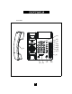
TOP PANEL (14) (2) (1) (3) (4) (5) (6) (7) (13) (8) (9) (12) 10 (11) (10)
1. Speed Dial Feature Keys……………..…… 11 programmable one-touch keys used for speed dialing 2. Disconnect Key ………………………...… Used to disconnect the line, place new call or exit the store programming. 3. Store Key………………………………….. Used to program features and speed dialing keys. 4. Pause Key ...............................…………… 5. Redial Key ......................…………….…... Redials the last dialed manually dialed. 6. Flash Key ..................…………….....…….
RIGHT SIDE LEFT SIDE REAR (7) (5) (6) LINE (1) (2) (3) (4) 12
1. Data Port .....................................…...………... Convenient port to connect a computer, modem, fax or answering device. 2. Line Jack ……………………………………... Modular receptacle for connecting the line cord. 3. Headset Jack .................................…………… Convenient port for a headset connection. 4. Handset Jack ..................................………….. Connection for handset coil cord. 5. Power Adapter Receptacle ……..…………… For optional coaxial power adapter. 6. Hold Key Switch ……………...
Parts Check List The following parts are included with the SpectrumPLUSTM SP400: Base Unit Handset Two (2) 15’ Modular telephone line cords. 10’ Modular coiled handset cord. 6” Modular wall mount line cord. Power Adapter. Twenty-two (22) Speed Dial Preprinted Keycaps Four (4) Additional Clear Keycaps Two (2) Index Sheets 1. Clear plastic overlay being remove from the index card area on the telephone. 2.Tearindexpaper fromtheindexsheet. 1 3. Lift off clear plastic keycap and insert the paper key label.
Caution ? Never install telephone wiring during a lightning storm. ? Never install telephone jacks in wet locations unless the jack is specifically designed for wet locations. ? Never touch uninstalled telephone wires or terminals unless the telephone line has been disconnected at the network interface. ? Use caution when installing or modifying telephone lines. Power Outlet Configuration The SpectrumPLUSTM Series telephone requires external power from a standard 120V outlet (60Hz).
120V AC Outlet Recovery Power Adapter (provided) The 120 VOLT AC OUTLET RECOVERY POWER ADAPTER is an featured TeleMatrix product. It provides both the telephone lines and the power source in one cable (6P6C line cord) and is designed to recover the use of the power outlet. Connector Configuration The 120V Outlet Recovery Power Adapter has two (2) modular jacks. One jack is labeled “LINE” and the other jack is labeled “PHONE”. These jacks allow for a fully modular installation.
Installing The Wall Power Adapter (optional) To install, simply plug the power adapter into a standard 120V AC power outlet. A mounting hole is provided to secure the power pack to the AC wall outlet. Plug the AC power pack directly into the wall outlet and then plug the coaxial connector into the receptacle marked “POWER” located on the back of the telephone.
Directory Index Card 1. Clear plastic overlay being remove from the index card area on the telephone. The SpectrumPlus TM telephone series has a tilting display located in the upper right section of the telephone that allows for sliding in directory cards, index cards, and/or a company logo. You can even personalize this area with photographs of your family, friends or pets. 2. Tear index paper from the index sheet.
Connecting the Handset Cord Handset Cord A 10 foot modular coil handset cord is provided. (Be sure that the wall/desk elevation stand has not been attached). To install the cord, simply plug the short end of the handset cord into the modular jack on the handset. The long end of the handset cord plugs into the jack labeled “Handset” located on the bottom of the SpectrumPLUSTM base unit. Place the line cord into the line cord channel located directly below the jack.
Wall Mounting the SpectrumPLUS TM Telephone The SpectrumPLUSTM was designed to be conveniently wall mounted without requiring additional hardware. Retaining Clip 1. 2. 3. PULL OUTWARD UNSNAP ROTATE 180 . SNAP INTO PLACE. CLIP IS SPRING LOADED Follow these easy steps: 1.The handset retaining clip must be in the correct position to secure the handset into the handset cradle.
Message Waiting Light Indicator MW Light Indicator The SpectrumPLUSTM telephone has a Message Waiting (MW) Light Indicator (figure 1). The indicator will blink to indicate that a new message is in the user’s voice mailbox. The SpectrumPLUSTM supports the following telephone or PBX supplied message waiting signals: 1. Telephone Company VMWI Servic e (FSK signal compatible, subscription to local telephone company is required).* 2. Audible Stutter Dial Tone (SDT) signals provided by local telephone company.
System Hold Feature Option Switch A hold feature switch is located on the bottom of the phone. The switch options are standard “LINE” hold or programmable* “SYSTEM” hold. The standard line hold allows for normal hold function operation. The programmable* system hold feature is used for optional system operations. The switch default is standard line hold. 22 * Programming System Hold is an Administrator function. To program System Hold, follow the speed dial instructions in this manual.
Programming Flash Timing into Memory Flash Timing can be programmed into the SpectrumPLUSTM speed dial memory. This function allows the user to dial a timed line break in the sequence of the dialing patterns when using the speed dial keys. This function may be required for accessing line features provided by your telephone system or local telephone company. Programming The Flash Timing To Program Flash Timing 1. Press the STORE key. 2.
Programming Flash Timing Flash timing can be programmed for different timing options listed below. 1. Position the handset in the Off-Hook position (lift the handset). 2. Press the “STORE” key for 2 seconds. 3.
Programming A Pause into Memory 2-second Pause(s) can be programmed into the speed dial. This function allows the user to delay the dialing pattern of a number. This function may be required for accessing line features provided by your telephone system or local telephone company. For example, a speed dial number may need to pause during its dialing sequence to insure proper connections. Programming Pause Into Speed Dial To Program A Timed Pause 1.
Programming Procedure For SpectrumPlus tm Speed Dial Features The SpectrumPLUSTM Telephone has 11 one-touch speed dial locations that are convenient for dialing frequently used telephone numbers. Each speed dial location can store up to 32 digits. Follow the procedure below for programming the speed dial information. Note 1: Speed dial programming must be done with the telephone plugged into the telephone line and power adapter. Note 2: Programming can be performed with the telephone on-hook.
Headset Feature The SpectrumPLUSTM is equipped with a separate port for plugging in an optional headset. The port is located on the bottom of the base unit. The TeleMatrix FreeSpeechTM Talk Feature is a unique TeleMatrix feature that allows the user the freedom to “toggle” between the headset, handset and speakerphone modes during a conversation. When the “HEADSET ON/OFF” key is ON, pressing the “SPEAKER” key will activate the speaker and disconnect the headset line automatically.
Using A Headset The “HEADSET ON/OFF” key controls the activation of the Headset. When using the headset feature, the handset remains on-hook at all times. Placing/Answering a Call using the Headset On/Off Feature ? ? ? ? ? To answer an incoming call, press the “HEADSET ON/OFF” key to activate the headset. The LED above the “HEADSET ON/OFF” key will be illuminated when in ON position. Adjust the volume, if necessary. Use the features of the headset that are available with the handset in use.
In-Use Indicators In-use indicator lights located above each key indicate in-use operations. Speaker Line Indicators When the “SPEAKER” key is activated, the in-use light illuminates steadily RED above the “SPEAKER” key. Hold Key Indicators When the “HOLD” key is activated, the light above the HOLD KEY will be steadily RED. Headset Key Indicators When the “HEADSET ON/OFF” key is activated, the Headset indicator will be steadily RED.
Placing a Call Using the Speakerphone The SpectrumPLUSTM is equipped with a high quality speakerphone feature to allow for hands-free operation. To use, simply press the “SPEAKER” key when placing or answering a call. The telephone line will activate automatically. When the “DIALPAD” Feature is programmed to be ON, the speakerphone will active automatically when pressing and number on the dial pad keys. The LED above the “SPEAKER” key will illuminate to indicate that the speakerphone is in-use.
Using the Data Port The SpectrumPLUSTM is equipped with a convenient data port on the bottom of the base unit. This modular receptacle is used to plug in any standard telephone device such as a computer modem, answering machine , or fax machine.
Using the Hold Feature The “HOLD” key is used to place a caller on hold. To use, simply press the “HOLD” key. The LED above the HOLD key will illuminate to indicate that the line is on hold. When the “HOLD” key is active, the handset can be lifted off-hook or returned to its on-hook position and the line will not be disconnected. To return to the caller, simply lift the handset and the “SPEAKER” key will automatically activate for hands-free operation.
Using The Mute Feature A “MUTE” key is provided to allow privacy during a background conversation. When the “MUTE” key is activated, the microphones in the handset and/or headset are disabled. When the “MUTE” key is activated, the caller will not hear voice. When activated, the LED above the Mute key will illuminate steadily RED. To de-activate, press the “MUTE” key again.
Using the Redial Feature The “REDIAL” key is used to automatically redial the last number that was dialed from the keypad. To use: ? ? ? Lift the handset (or activate the speaker). Press the “REDIAL” key. The last number dialed will be redialed.
Using The Disconnect Feature Key The “DISC” (DISCONNECT) key is a 2-second electronic timed line break. The key can be used to automatically hang-up the call that you are currently on and regain a new dial tone to establish a new call. To use: ? ? ? ? Simply press the “DISC” key when the conversation is complete. The “DISC” key can be used in Speaker mode, on-hook, off-hook or conference. The “DISC” key can be used with headset or handset activation.
Handset Volume Control The SpectrumPLUSTM is equipped with an ADA/FCC compliant handset volume control located on the front of the phone. When the right end of the “VOLUME” key is pressed, the volume of the handset receiver is increased. When the left end of the “VOLUME” key is pressed, the volume of the handset receiver is decreased. The “VOLUME” key is an eight-step volume control with the “1” setting being OFF.
Keep the telephone dry. If it gets wet, wipe it dry immediately. Liquids might contain minerals that can corrode the electronic circuits. Use and store the telephone only in normal temperature environments. Temperature extremes can shorten the life of electronic devices, damage batteries, and distort or melt plastic parts. Keep the telephone away from excessive dust and dirt that can cause premature wear of parts. Wipe the telephone with a damp cloth occasionally to keep it looking new.
When problems arise during installation or service that cannot be resolved using this or related documents, contact the TeleMatrix Technical Service department 8:30a.m. - 4:30p.m. MST: Toll Free: 1-800-462-9446 Direct: 719-638-8821 Fax: 719-638-8815 www.telematrixusa.com Many times a problem is either installation or user related. Please contact TeleMatrix PRIOR to sending a telephone to our service center for repair. In the unlikely event that a factory repair be necessary: 1.
Parts List The following SpectrumPLUStm accessories and parts are available from TeleMatrix.
STATEMENT OF LIMITED WARRANTY TeleMatrix, Inc.