User’s Manual Pub. 0300246-01 Rev.
ii MicroLogix™ 1200 8 Ch Output Module Important Notes 1. Please read all the information in this owner’s guide before installing the product. 2. The information in this owner's guide applies to hardware Series A and firmware version 1.00 or later. 3. This guide assumes that the reader has a full working knowledge of the relevant processor. Notice The products and services described in this owner's guide are useful in a wide variety of applications.
iii Table of Contents IMPORTANT NOTES............................................................................................................................................ II NOTICE .............................................................................................................................................................. II LIMITED WARRANTY ..........................................................................................................................................
iv MicroLogix™ 1200 8 Ch Output Module PREFACE Read this preface to familiarize yourself with the rest of the manual.
v Conventions Used in This Manual The following conventions are used throughout this manual: Bulleted lists (like this one) provide information not procedural steps. Numbered lists provide sequential steps or hierarchical information. Italic type is used for emphasis Bold type identifies headings and sub-headings ! Attention Are used to identify critical information to the reader User’s Manual Pub. 0300246-01 Rev.
vi MicroLogix™ 1200 8 Ch Output Module User’s Manual Pub. 0300246-01 Rev.
Chapter 1 Module Overview This chapter describes the 1762sc-OF8 output module. The module provides 8 analog output channels that can be configured for current or voltage. Included is information about: General description Output types and ranges Data Formats Hardware Features System overview and module operation Section 1.1 General Description The output module supports current and voltage type outputs.
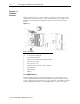
1-2 MicroLogix™ 1200 IO 8 Ch Output Module Section 1.4 Hardware Features Module configuration is done via the controller’s programming software. The module configuration is stored in the memory of the controller. Refer to your controller’s user manual for more information. The illustration below shows the module’s hardware features.
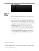
Chapter 1: Module Overview 1-3 Table 1-1 (LED Blink Codes) Blink Code Description 1 Rapid Blink PLC not in run mode, or no valid module configuration present Solid Module is in run mode (Normal Operation) 3 Factory calibration in progress 4 Factory calibration invalid 5 Module is in command mode Section 1.5 System Overview The module communicates to the controller through the bus interface. The module also receives 5 and 24V dc power through the bus interface. 1.5.
1-4 MicroLogix™ 1200 IO 8 Ch Output Module 1.5.2 Module Operation When the module receives a new command value from the output image, the module’s circuitry converts the digital value to an analog current/voltage signal using a DAC (Digital to Analog Converter). See the block diagram below. User’s Manual Pub. 0300246-01 Rev.
Chapter 2 Installation and Wiring This chapter will cover: Compliance to European union directives Power requirements General considerations Mounting Field wiring connections Module Indicators Section 2.1 Compliance to European Union Directives This product is approved for installation within the European Union and EEA regions. It has been designed and tested to meet the following directives. 2.1.
2-2 MicroLogix™ 1200 IO 8 Ch Output Module 5 VDC 24 VDC 30 mA 250 mA @ 18.7V, 195mA @ 24V Use the table below to determine the maximum number of OF8 modules that can be installed in a MicroLogix system. Table 2-1 Controller ML1100 ML1200 (24pt.) ML1200 (40pt.) ML1400 (ALL) Max 5V Bus Current (mA) 800 400 600 1500 Max 24V Bus Current (mA) 700 350 500 1500 Max # of OF8 Modules 3 1 2 6 Section 2.
Chapter 2: Installation and Wiring 2-3 2.3.2 Prevent Electrostatic Discharge ! Attention Electrostatic discharge can damage integrated circuits or semiconductors if you touch analog I/O module bus connector pins or the terminal block on the input module. Follow these guidelines when you handle the module: Touch a grounded object to discharge static potential. Wear an approved wrist-strap grounding device. Do not touch the bus connector or connector pins.
2-4 MicroLogix™ 1200 IO 8 Ch Output Module 2.4.1 Minimum Spacing Maintain spacing from enclosure walls, wireways, adjacent equipment, etc. Allow 50.8 mm (2 in.) of space on all sides for adequate ventilation, as shown: Figure 2-1 Note: 1762 expansion I/O may be mounted horizontally only. ! Attention During panel or DIN rail mounting of all devices, be sure that all debris (metal chips, wire strands, etc.) is kept from falling into the module.
Chapter 2: Installation and Wiring 2-5 Figure 2-2 Note: For environments with extreme vibration and shock concerns, use the panel mounting method described below, instead of DIN rail mounting. 2.4.3 Panel Mounting Use the dimensional template shown below to mount the module. The preferred mounting method is to use two M4 or #8 Pan Head screws per module. M3.5 or #6 Pan Head screws may also be used, but a washer may be needed to ensure a good ground contact. Mounting screws are required on every module.
2-6 MicroLogix™ 1200 IO 8 Ch Output Module Figure 2-4 Note: Use the pull loop on the connector to disconnect modules. Do not pull on the ribbon cable. EXPLOSION HAZARD In Class I, Division 2 applications, the bus connector must be fully seated and the bus connector cover must be snapped in Attention place. In Class I, Division 2 applications, all modules must be mounted in direct contact with each other as shown on page 24.
Chapter 2: Installation and Wiring 2-7 USE SUPPLY WIRES SUITALE FOR 20°C ABOVE SURROUNDING AMBIENT ! Attention ! Attention UTILISER DES FILS D’ALIMENTATION QUI CONVIENNENT A UNE TEMPERATURE DE 20°C AU-DESSUS DE LA TEMPERATURE AMBIANTE Grounding This product is intended to be mounted to a well-grounded mounting surface such as a metal panel. Additional grounding connections from the module’s mounting tabs or DIN rail (if used) are not required unless the mounting surface cannot be grounded.
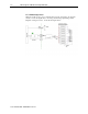
2-8 MicroLogix™ 1200 IO 8 Ch Output Module Shield RTN 0 RTN 1 RTN 2 RTN 3 OUT 0 Load OUT 1 + - OUT 2 OUT 3 NC NC RTN 4 RTN 5 RTN 6 RTN 7 OUT 4 OUT 5 OUT 6 OUT 7 Note: All return terminals are electrically tied together, but each output should use its own associated return terminal for best accuracy. User’s Manual Pub. 0300246-01 Rev.
Chapter 2: Installation and Wiring 2-9 2.6.2 Wiring the Finger-Safe Terminal Block Figure 2-6 ! Attention Be careful when stripping wires. Wire fragments that fall into a module could cause damage when power is applied. Once wiring is complete, ensure the module is free of all metal fragments. When wiring the terminal block, keep the finger-safe cover in place. 1) Refer to section 2.6.1for proper field wiring connections. 2) Route the wire under the terminal pressure plate.
2-10 MicroLogix™ 1200 IO 8 Ch Output Module Figure 2-7 (Door Label) Section 2.7 Module Indicators The 1762 output module uses a single green LED to show operational status of the module. The LED will illuminate solid when the PLC is in run mode and the module properly configured. If the module is not properly configured, or if the PLC is not in run mode, the LED will blink rapidly.
Chapter 3 Configuring the 1762sc-OF8 Using RSLogix 500 This chapter covers the following subjects: Things you should know Module memory map Add module to Logix 500 Module configuration Module status Configuration Ladder Sample Section 3.1 Things You Should Know This chapter describes how to configure the OF8 module for the MicroLogix 1100, 1200 and 1400 system using RSLogix 500 programming software. Section 3.
3-2 MicroLogix™ 1200 IO 8 Ch Output Module Section 3.3 Add Module to Logix 500 The following procedure describes how to add the OF8 module to the RSLogix 500 programming software. 1.) Create a new RSLogix 500 project and select either a Micro 1100, 1200, or 1400 processor. 2.) Double-click “I/O Configuration” from the project tree. 3.) Select the first empty slot and then double-click the “Other—Requires I/O Card Type ID” option, from the I/O configuration screen. 4.
Chapter 3: Configuring the 1762sc-OF8 for RSLogix 500 3-3 5.) Repeat steps 1 through 4 for additional modules. Section 3.4 Module Configuration The OF8 module is configured using a process that employs the input and output files. The following flow chart describes the configuration process.
3-4 MicroLogix™ 1200 IO 8 Ch Output Module 3.4.1 Output Data File (Command Mode) The output data file is used to configure each channel for the OF8 as well as control the output signal of each channel. Use the addressing scheme below to locate the 8 output words needed to configure the module. Figure 3-2 (Output Addressing Scheme) (1) I/O located on the controller (embedded I/O) is slot 0. I/O added to the controller (expansion I/O) begins with slot 1.
Chapter 3: Configuring the 1762sc-OF8 for RSLogix 500 3-5 2) Validate Command: If the Fixed Words are valid, the Command word will be checked. If it is not set to a valid command, an error will be reported. Initially the module only checks for the Unlock command. After the Unlock command is detected, the module must detect a transition in the Command word to trigger a new command. The available commands are listed in the table below.
3-6 MicroLogix™ 1200 IO 8 Ch Output Module Table 3-3 (Data Words 1 through 4) To Select Channels 1, 3, 5, or 7 15 Output Type 14 13 12 11 4 to 20 mA 9 0 8 0 0 to 20 mA 0 0 -10 to 10 V 0 1 0 to 10 V 0 1 to 5 V 0 to 5 V Reserved Channel Disabled Data Format Channels 0, 2,4 or 6 10 0 7 6 5 4 3 2 0 1 0 0 0 1 0 0 1 0 0 1 0 1 1 0 1 1 1 0 0 1 0 0 1 0 1 1 0 1 1 1 0 1 1 0 1 1 1 1 1 1 Scaled for PID 0 0 0 0 Engineering Units 0 1 0 1 Percen
Chapter 3: Configuring the 1762sc-OF8 for RSLogix 500 3-7 Table 3-4 (Data Format) Output Range 4..20mA 0..20mA +/-10V 0 to 5V 0 to 10V 1 to 5V Output Value 20.40 mA Condition High Limit Raw/Prop 32767 EU 20400 PID 16793 % FS 10250 20.00 mA High Range 31176 20000 16383 10000 4.00 mA Low Range -32450 4000 0 0 3.92 mA Low Limit -32768 3920 -82 -50 20.40 mA High Limit 32767 20400 16711 10200 20.00 mA High Range 31482 20000 16383 10000 0.
3-8 MicroLogix™ 1200 IO 8 Ch Output Module Figure 3-3 (Input Addressing Scheme) (1) I/O located on the controller (embedded I/O) is slot 0. I/O added to the controller (expansion I/O) begins with slot 1. The layout for the input data file is shown below. Table 3-5 (Input Data File) Input Word Normal Run Mode Command Mode I:e.0 General Status Word 0 Command Echo I:e.1 Output Status Word 1 (ch 0-3) Response Code I:e.2 Output Status Word 2 (ch 4-7) Response Channel I:e.3 Echo Config (ch 0-1) I:e.
Chapter 3: Configuring the 1762sc-OF8 for RSLogix 500 3-9 Table 3-7 (Response Codes) Name Value Description Success 0x0000 The command was completed successfully. Invalid Command 0xF001 An invalid command code was issued. A command was issued before the Unlock was Locked 0xF002 given. One or more Fixed Words invalid. The module will Invalid State 0xF003 remain in its previous state until all of the words are set correctly. A configuration for one of the channels is invalid.
3-10 MicroLogix™ 1200 IO 8 Ch Output Module Table 3-8 (Input Words - Normal Run Mode) Word Bit 15 14 13 12 11 10 9 8 7 6 5 4 3 2 1 0 General Status (Word 0) I:e.0 - S7 S6 S5 S4 S3 S2 S1 S0 Output Status (Word 1) I:e.1 - LD3 U3 O3 - LD2 U2 O2 - LD1 U1 O1 - LD0 U0 O0 Output Status (Word 2) I:e.
Chapter 3: Configuring the 1762sc-OF8 for RSLogix 500 User’s Manual Pub. 0300246-01 Rev.
3-12 MicroLogix™ 1200 IO 8 Ch Output Module User’s Manual Pub. 0300246-01 Rev.
Chapter 3: Configuring the 1762sc-OF8 for RSLogix 500 User’s Manual Pub. 0300246-01 Rev.
3-14 MicroLogix™ 1200 IO 8 Ch Output Module User’s Manual Pub. 0300246-01 Rev.
Appendix A Module Specifications General Specifications Specification Value Dimensions 90 mm (height) x 87 mm (depth) x 40 mm (width) height including mounting tabs is 110 mm 3.54 in. (height) x 3.43 in. (depth) x 1.58 in. (width) height including mounting tabs is 4.33 in. Approximate Shipping Weight (with carton) 279g (0.615 lbs.
A-2 MicroLogix™ 1200 IO 8 Ch Output Module Specification Product Code Agency Certification Hazardous Environment Class Radiated and Conducted Emissions Electrical /EMC: ESD Immunity (IEC61000-4-2) Radiated Immunity (IEC61000-4-3) Fast Transient Burst (IEC61000-4-4) Surge Immunity (IEC61000-4-5) Conducted Immunity (IEC61000-4-6) 8 Value 21 C-UL listed (under CSA C22.2 No. 142) UL 508 listed CE compliant for all applicable directives Class I, Division 2, Hazardous Location, Groups A, B, C, D (ISA 12.12.
Appendix A: Specifications Output Specifications Specification Accuracy - Voltage Outputs Accuracy - Current Outputs Output Resolution (at 25C) Voltage Output Current Output Differential Nonlinearity Output Ripple Output Impedance Output Load Maximum Output Inductive and Capacitive Load Output Settling Time Output Channel glitch Output Protection Short Circuit Protection User’s Manual Pub. 0300246-01 Rev.
A-4 MicroLogix™ 1200 IO 8 Ch Output Module User’s Manual Pub. 0300246-01 Rev.
A L Addressing ∙ 3‐4, 3‐7, 3‐9 LED ∙ 1‐2, 2‐10 Low Voltage Directive ∙ 2‐1 B M block diagram ∙ 1‐4 C Memory Map ∙ 3‐1 Mounting DIN ∙ 2‐4 Panel ∙ 2‐5 Configuration ∙ 3‐4 N D Data Format ∙ 1‐1 Door Label ∙ 2‐9 E EMC Directive ∙ 2‐1 G Noise ∙ 2‐3, 2‐7 O Output Type ∙ 1‐1 P Power Requirements ∙ 2‐1 power‐up ∙ 1‐3 Grounding ∙ 2‐7 S H Hazardous Location ∙ 2‐2 Slot number ∙ 3‐4 Slot Number ∙ 3‐8 Spacing Minimum ∙ 2‐4 I Input Data ∙ 3‐7 W Wiring Diagram ∙ 2‐7 User’s Manual Pub. 0300246-01 Rev.
User’s Manual Pub. 0300246-01 Rev.
Getting Technical Assistance Note that your module contains electronic components which are susceptible to damage from electrostatic discharge (ESD). An electrostatic charge can accumulate on the surface of ordinary plastic wrapping or cushioning material. In the unlikely event that the module should need to be returned to Spectrum Controls, please ensure that the unit is enclosed in approved ESD packaging (such as static-shielding / metalized bag or black conductive container).
©2009, Spectrum Controls, Inc. All rights reserved. Specifications subject to change without notice. The Encompass logo and ControlLogix are trademarks of Rockwell Automation. Corporate Headquarters Spectrum Controls Inc. P.O. Box 6489 Bellevue, WA 98006 USA Fax: 425-641-9473 Tel: 425-746-9481 Web Site: www.spectrumcontrols.com E-mail: spectrum@spectrumcontrols.com User’s Manual Pub. 0300246-01 Rev.