
Owner manual

1-2 MicroLogix™ 1200 IO 8 Ch Output Module
User’s Manual Pub. 0300246-01 Rev. B
Section 1.4
Hardware
Features
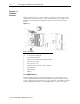
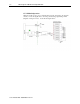
Module configuration is done via the controller’s programming software. The module
configuration is stored in the memory of the controller. Refer to your controller’s user
manual for more information. The illustration below shows the module’s hardware
features.
Item Description
1a Upper panel mounting tab
1b Lower panel mounting tab
2 Power diagnostic LED
3 Module door with terminal identification label
4 Bus connector (male)
5 Bus connector cover
6 Flat ribbon cable with bus connector (female)
7 Terminal block
8 DIN rail latch
9 Pull loop
1.4.1 LED Indicator
The 1762 output module uses a single green LED to show operational status of the
module. The LED will illuminate solid when the PLC is in run mode and the module
properly configured. If the module is not properly configured, or if the PLC is not in run
mode, the LED will blink rapidly. The following blink codes are the only exception:
Fi
g
ure 1-1