
Owner manual

Chapter 1: Module Overview 1-3
User’s Manual Pub. 0300246-01 Rev. B
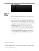
Table 1-1 (LED Blink Codes)
Blink Code Description
Rapid Blink
1
PLC not in run mode, or no valid module configuration present
Solid Module is in run mode (Normal Operation)
3 Factory calibration in progress
4 Factory calibration invalid
5 Module is in command mode
Section 1.5
System
Overview
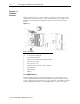
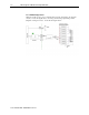
The module communicates to the controller through the bus interface. The module also
receives 5 and 24V dc power through the bus interface.
1.5.1 Module Power-up
At power-up, the module performs a check of its internal circuits, memory, and basic
functions. During this time, the module status LED remains off. If no faults are found
during power-up diagnostics, the module status LED blinks rapidly waiting for command
mode.
After power-up checks are complete, the module waits for command mode and then valid
channel configuration data. If an invalid configuration is detected, the module generates
a configuration error and remains in command mode. Once the module is properly
configured and enabled, it continuously converts the output command value to a
proportional analog output signal.
Each time a channel command value is read by the output module, that data value is
tested by the module for an over-range or under-range condition. If such a condition is
detected, a unique bit is set in the channel status word. The channel status word is
described in section 3.5.2 Input Data File.
Using the module image table, the controller reads the two’s complement binary
converted input data from the module. This typically occurs at the end of the program
scan or when commanded by the control program. If the controller and the module
determine that the data transfer has been made without error, the data is used in the
control program.
1
All outputs are disabled until the PLC goes into run mode and the module receives a valid configuration.