Install Guide Micro800™ 4 Ch Universal Thermistor Input Module (Catalog Number 2080sc-NTC) Table of Contents For More Information ................................................................................. 1 Environment and Enclosure ...................................................................... 2 Prevent Electrostatic Discharge ................................................................ 3 Parts List .......................................................................................
Micro800™ 4 Ch Universal Thermistor Input Module 2 Environment and Enclosure ATTENTION This equipment is intended for use in a Pollution Degree 2 industrial environment, in overvoltage Category II applications (as defined in IEC publication 60664-1), at altitudes up to 2000 meters (6562 feet) without derating. This equipment is considered Group 1, Class A industrial equipment according to IEC/CISPR Publication 11.
Micro800™ 4 Ch Universal Thermistor Input Module 3 Prevent Electrostatic Discharge WARNING Electrostatic discharge can damage integrated circuits or semiconductors if you touch bus connector pins. Follow these guidelines when you handle the module: Touch a grounded object to discharge static potential. Wear an approved wrist-strap grounding device. Do not touch connectors or pins on component boards. Do not touch circuit components inside the module.
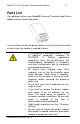
Micro800™ 4 Ch Universal Thermistor Input Module 4 Parts List Your package contains one Micro800 Universal Thermistor Input Plug-in Module and one Quick Start guide. You can choose to wire the plug-in before inserting it onto the controller, or wire it once the module is secured in place. WARNING This equipment is considered Group 1, Class A industrial equipment according to IEC/CISPR 11.
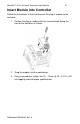
Micro800™ 4 Ch Universal Thermistor Input Module 5 Insert Module into Controller Follow the instructions to insert and secure the plug-in module to the controller. 1. Position the plug-in module with the terminal block facing the front of the controller as shown. 2. Snap the module into the module bay. 3. Using a screwdriver, tighten the 10…12 mm (0.39…0.47 in.) M3 self-tapping screw to torque specifications. Publication 0100198-01 Rev.
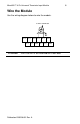
Micro800™ 4 Ch Universal Thermistor Input Module Wire the Module Use the wiring diagram below to wire the module. 2-wire Thermistor IN +2 IN -2 IN +0 ATTENTION IRET2 IN -0 IN +3 IRET0 IN -3 IN +1 IRET3 IN -1 IRET1 IRET0 to IRET3 are reserved for a later date. Publication 0100198-01 Rev.
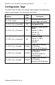
Micro800™ 4 Ch Universal Thermistor Input Module 7 Configuration Tags This table shows the tags in the sample ladder program for configuration. Details are described in the sub-sections that follow. Register Data Type Comments S1_CFG_Trigger INT Transition from 0 to nonzero to trigger new config.
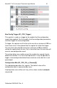
Micro800™ 4 Ch Universal Thermistor Input Module 8 New Config Trigger (S1_CFG_Trigger) This register is used as a trigger to the module that the configuration needs to be applied. You first modify all of the configuration parameters, and then trigger the new configuration. To trigger, the register must first be set to zero for a minimum of 300 ms. A non-zero value is then placed into the register to initiate the trigger.
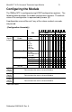
Micro800™ 4 Ch Universal Thermistor Input Module 9 Configuring the Module The 2080sc-NTC is configured using 8 SINT configuration registers. The following table describes the module configuration registers. The default value of the configuration is represented by zeroes (0). A configuration error will be set if any of the values marked are passed. (Configuration Assembly) 15 14 13 12 11 10 9 8 7 6 5 4 3 2 1 0 MSB LSB 7 6 5 4 3 2 1076543210 Ch0 Channel Enable 0 Config.
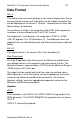
Micro800™ 4 Ch Universal Thermistor Input Module 10 Data Format EU x1 This displays the measured readings in their natural integer form. Due to the measurement range and 16-bit data size, the highest resolution that can be displayed for resistance is 10 ohms. Temperatures will have two decimal places of resolution. For resistance, it will be in the range from 0 to 32767 which represents resistance in ohms divided by ten (0 to 327.67 k ohms).
Micro800™ 4 Ch Universal Thermistor Input Module 11 Temperature in Kelvin is determined by the following formula: ( ) B = User-supplied BETA parameter R0 = User-supplied resistance at room temperature (T0). T0 = (constant) Room temperature (25˚ C) in Kelvin (298.15). R = Measured resistance. After solving for T, it is then converted to Celsius: T - 273.15 Steinhart-Hart If the Equation is set to Steinhart-Hart, all three COEFF strings are used.
Micro800™ 4 Ch Universal Thermistor Input Module 12 The value is a signed, 16-bit integer. It represents temperature in degrees Celsius multiplied by 100 when the Equation is not set to Resistance. If the Equation is set to Resistance, the values represent ohms divided by 10. The Maximum cannot be not be equal to, or less than, the Minimum. An invalid configuration is set in that case. This format allows for temperature spans from +327.67C to -327.68C.
Micro800™ 4 Ch Universal Thermistor Input Module 13 The size of the string may be up to 16 characters. It is not necessary to terminate with NULL. A valid floating point number string is formed by a succession of: An optional plus or minus sign. A sequence of numeric digits, optionally containing a single decimal-point character. An optional exponent part, which itself consists on an 'e' or 'E' character followed by an optional sign and a sequence of digits.
Micro800™ 4 Ch Universal Thermistor Input Module 14 The following table lists the memory location offset for each parameter which is used when configuring the PLUGIN_READ, WRITE, and INFO instructions.
Micro800™ 4 Ch Universal Thermistor Input Module Parameter Offset (Dec) 15 Comments Default MOD_OUTPUT_OFFSET 25 Starting address offset of Output Registers MOD_INPUT_LATCH 26 Writing with 0xA5 to this register will trigger input latch 27 Writing with 0xA5 to this register will trigger output latch 0 MOD_INTERRUPT_CONF 28 Writing to this register will enable/disable module interrupt to controller 0 MOD_GC_DATA_LENGTH_LB 29 Low byte of the generic configuration data length 218 MOD_GC_DA
Micro800™ 4 Ch Universal Thermistor Input Module 16 Module Error Register (MOD_STATUS) The Micro800™ 4 Ch Universal Thermistor Input Module is available in only one configuration: 2080-sc-NTC. The module uses the following parameters: Bit Number 0 to 1 2 Description Notes These 2 bits define module operation mode: 3 is not supported 0: Idle: Module is ready to RUN, and I/O is off. 2: Error: Error happens and I/O is off. 3: Busy: Module is busy, cannot go to RUN, and I/O is off. See Notes.
Micro800™ 4 Ch Universal Thermistor Input Module 17 Output Block (0x30 [48] to 0x3F [63]) Register RESERVED Address Comments 0x30 [48] to 0x3F [63] Output words are not used on this module but the block space is reserved Status Block (0x40 [64] to 0x4F [79]) Register Address Comments OC_STATUS 49 Open circuit status. See Open Circuit Status Register (OC_STATUS) information below. UO_STATUS 50 Under/Over Range Status. See information below.
Micro800™ 4 Ch Universal Thermistor Input Module 18 Under/Over Range Status Register (S1_STS_CHAN_OU) These status bits are dependent on the setting of the Maximum and Minimum user values. If the displayed value is greater than Maximum, the ‘O’ bit shall be set for the channel. If the displayed value is less than Minimum, the ‘U’ bit shall be set for the channel. Word/Bit 7 6 5 4 3 2 1 0 O3 O2 O1 O0 U3 U2 U1 U0 Bit 0 is for channel 0 under range indication.
Micro800™ 4 Ch Universal Thermistor Input Module Register S1_CFG_CH_n_String[0] (CH0 COEFF-A/BETA) 19 Byte Address Size (Bytes) Data Type Comments 88-103 16 STRING -COEFF-A for Steinhart-Hart Equation -BETA for BETA Equation 104-119 16 STRING -COEFF-B for Steinhart-Hart Equation -Resistance @25C for BETA Equation 120-135 16 STRING -COEFF-C for Steinhart-Hart Equation Ignored for BETA Equation See above 136-189 54 - Channel 1 Config Block See above 190-243 54 - Channel 1 Config Blo
Micro800™ 4 Ch Universal Thermistor Input Module 20 Analog Data (S1_Input_CH_n) These registers display the current analog reading. The following sample program, written in structured text, demonstrates how to configure the module in CCW. Controller.Micro830.Micro830.Main (*********************************************) (* FIRST TIME *) (*********************************************) FirstScanTimer(true, T#1ms); IF (FirstScanTimer.
Micro800™ 4 Ch Universal Thermistor Input Module 21 (* Translate channel configurations. *) FOR chan_idx := 0 TO 3 BY 1 DO (* Copy the 3 word parameters.
Micro800™ 4 Ch Universal Thermistor Input Module 22 tmp_result := ANY_TO_DINT(raw_input_array[idx+1]); tmp_result := SHL(tmp_result, 8); tmp_result := tmp_result + ANY_TO_DINT(raw_input_array[idx]); CASE i OF 0: S1_Input_CH_0 := ANY_TO_INT(tmp_result); 1: S1_Input_CH_1 := ANY_TO_INT(tmp_result); 2: S1_Input_CH_2 := ANY_TO_INT(tmp_result); 3: S1_Input_CH_3 := ANY_TO_INT(tmp_result); END_CASE; idx := idx +2; END_FOR; (*********************************************) (* STATUS *) (*****************************
Micro800™ 4 Ch Universal Thermistor Input Module Input Specifications CMRR Values < 1% reading error with 10 Vp-p input; 50 Hz and 60 Hz for 4 Hz and 16 Hz filters NMRR No NMRR requirement for this module Crosstalk -70 dB maximum Output Source Voltage 2.5 V @ 25°C, ±3% from -20°C to 65°C Input protection Voltage Mode 24 VDC continuous. Power source 3.3 VDC, 26 mA from backplane, and 24 VDC, 10 mA from backplane. Channel to Channel Isolation None Inrush current <500 mA at 3.
Micro800™ 4 Ch Universal Thermistor Input Module Environmental Specifications Environmental Tests Temperature (Operating) (Performance Criteria A) Industry Standards Test Level Limits IEC60068-2-1: (Test Ad, Operating Cold), -20° C to 65° C (-4° F to 149° F) IEC60068-2-2: (Test Bd, Operating Dry Heat), IEC60068-2-14: (Test Nb, Operating Thermal Shock) Temperature IEC60068-2-1: (Non-operating) (Performance Criteria B) (Test Ab, Unpackaged Non-operating Cold), -40° C to 85°C (-40° F to 185° F) IEC
Micro800™ 4 Ch Universal Thermistor Input Module Environmental Tests Conducted Emissions ESD immunity Industry Standards Test Level Limits IEC 61000-6-4:2007 FCC 47 CFR part 15 Class A Group 1, Class A (AC Mains), 150 kHz – 30 MHz IEC 61000-4-2 6 kV Indirect (Coupling Plate) (Performance Criteria B) 6 kV Contact Discharge ( to points of initial contact) 8 kV Air Discharge (to points of initial contact) Radiated RF immunity IEC 61000-4-3: Level 3 (Performance Criteria A) 10 V/M with 1 kHz sine-wa
Micro800™ 4 Ch Universal Thermistor Input Module Environmental Tests EFT/B immunity Industry Standards IEC 61000-4-4 (Performance Criteria B) Test Level Limits Signal Ports: ± 3 kV @ 5 kHz for 5 minutes, Criteria B (Marine?) ± 2 kV @ 5 kHz for 5 minutes, Criteria A (Marine?) ± 2 kV @ 5 kHz for 5 minutes, Criteria B (standard) Power Ports: ± 2 kV @ 5 kHz for 5 minutes, Criteria A (Marine?) ± 2 kV @ 5 kHz for 5 minutes, Criteria B (standard) Surge transient immunity IEC 61000-4-5 Signal Ports: ± 2 kV li
Micro800™ 4 Ch Universal Thermistor Input Module Safety Tests Industry Standards UL Safety UL 508 Industrial Control Equipment Seventeenth Edition Dated January 28 1999, with revisions through July 11, 2005 (ANSI/UL 508-2005) (NRAQ, NRAQ7) 27 Test Level Limits UL Safety cUL CSA C22.2 No. 142 -M1987 Process Control Equipment May 1987 UL Hazardous Locations ULH ANSI/ISA–12.12.
Micro800™ 4 Ch Universal Thermistor Input Module 28 Environnements dangereux Cet équipement est conçu pour être utilisé dans des environnements de Classe I, Division 2, Groupes A, B, C, D ou non dangereux. La mise en garde suivante s’applique à une utilisation dans des environnements dangereux. MISE EN GARDE DANGER D’EXPLOSION La substitution de composants peut rendre cet équipement impropre à une utilisation en environnement de Classe 1, Division 2.
Micro800™ 4 Ch Universal Thermistor Input Module Publication 0100198-01 Rev.
Micro800™ 4 Ch Universal Thermistor Input Module For Technical Support USA United Kingdom Australia Mexico Brazil Europe 440-646-6900 01908 635230 1800-809-929 001-888-365-8677 (55) 11 3618 8800 (49) 2104 960 630 1705 132nd Ave NE Bellevue, WA 98005 USA Tel: 425-746-9481 Fax: 425-641-9473 Email: spectrum@spectrumcontrols.com Web: www.spectrumcontrols.com Micro800 is a trademark of Rockwell Automation. Publication 2080sc-NTC Install Guide – April 2013 © 2013 Spectrum Controls, Inc. Printed in the USA.