
PowerSafe Telemetry Receiver Manual


EN
7
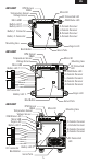
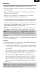
Installation
1. Find a secure mounting location on a mounting tray or bulkhead
2. Self tapping mounting screws are provided to use the integrated mounting
tabs and grommets.
3. We recomend drilling a pilot hole for the mounting screws to prevent the
mounting surface from splitting.
TIP: If the screw is threading into a soft material such as balsawood,
harden the threads with thin CA before final mounting.
4. It is not neccesary to compress the grommets tightly. Use a 2mm hex driver
to install the mounting screws so the grommets are gently compressed.
5. Secure the remote receivers so they are perpendicular from each other and
located away from conductive materials. It is best to locate the remotes in
different parts of the aircraft for best performance.
TIP: If you have telemetry link performance issues, inspect and/or relocate
the SPM4651T remote receiver to optimize performance in your aicraft.
NOTICE: Do not cut the antenna wire or allow it to kink on the SPM4651T
remote receiver. The last 31mm of the wire is the active portion of the
antenna. The coaxial wire leading up to antenna will be damaged if it is cut
or kinked.
6. Mount the soft switch on the side of your aircraft and insert the switch plug
in the port marked SWITCH.*
Soft Switch
*The PowerSafe receiver uses a specific switch. Conventionally wired switches
are not compatible with the PowerSafe receiver.
• The Soft Switch is a failsafe switch, it opens the circuit to power ON the
receiver. If a switch failure occurs during operation, the system will fail to
the ON position.
• The trickle current when the receiver is powered OFF is negligible and
will not affect the charge status during a flying session. However, always
unplug the batteries from the receiver at the end of a flying session.
• Connect the lead labeled Switch into the receivers Switch port. The
second lead labeled LED PWR can be connected to any of the receiver
ports that are powered to provide power to the switches LED which
can be used to see at a glance that the system is powered on from the
switch. The switch LED is optional, if not used simply secure the LED
PWR lead.
NOTICE: Failure to unplug the receiver batteries after a flying session will
result in a trickle current that will slowly drain the receiver battery. An over-
discharged battery should never be recharged.