
Instruction manual

8
SPEKTRUM DX5e • RADIO USER’S GUIDE
ENDEFRIT
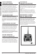
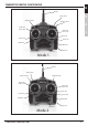
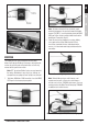
DIGITAL TRIMS
The DX5e features digital trims. Each time a trimmer is
moved the servo output will change one step. If the trimmer
is held, the output will scroll in that direction until the
trimmer is released or the output reaches its end.
Rudder Trim
Elevator Trim
Throttle Trim
Aileron Trim
Mode 2
Rudder Trim
Throttle Trim
Elevator Trim
Aileron Trim
Mode 1
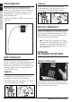
LOW BATTERY ALARM
When the battery voltage drops below 4.7 volts, an alarm
will sound and the voltage LEDs will flash.
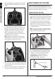
TRAINER
The DX5e offers a trainer function that allows the transmitter
to operate as a master or slave. The trainer switch is located
on the top of the transmitter, on the left side for Mode 2 and
the right side for Mode 1. When using the trainer function,
plug the trainer cord (SPM6805) into the trainer port in both
the master (controlling) and the slave (training) transmitters.
The master transmitter must have the power turned on and
the slave transmitter must have the power turned off.
Note: The DX5e trainer system is compatible with all
JR and Spektrum transmitters.
MASTER
The DX5e transmitter can be used as a master but the slave
transmitter must have the same programming (i.e. reverse
switch positions) as the master.
SLAVE
When using the DX5e transmitter as a slave with another
DX5e, it’s necessary to match all the reverse switch
positions.
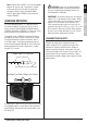
RECEIVER INSTALLATION
The AR600 incorporates dual receiver antennas, offering
the security of dual path RF redundancy. By locating these
antennas in slightly different locations in the aircraft, each
antenna is exposed to its own RF environment, greatly
improving path diversity (the ability for the receiver to see
the signal in all conditions).
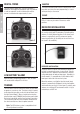
RECEIVER INSTALLATION
Install the receiver using the same method you would use
to install a conventional receiver in your aircraft. Typically,
wrap the receiver in protective foam and fasten it in place
using rubber bands or hook and loop straps. Alternately, in
electric models, it’s acceptable to use thick double-sided
foam tape to fasten the main receiver in place.
Mount the antennas such that the tip of the feeder (long)
antenna is perpendicular (90 degrees) to the short antenna
and the antennas are at least 2 inches apart. Essentially, each
antenna sees a different RF environment and this is key to
maintaining a solid RF link.