6 ® 6 Instruction Manual Bedienungsanleitung Manuel d’utilisation Manuale di Istruzioni Manual de instrucciones ®
EN NOTICE All instructions, warranties and other collateral documents are subject to change at the sole discretion of Horizon Hobby, LLC. For up-to-date product literature, visit horizonhobby.com and click on the support tab for this product.
EN DX6 Features • • • • • • • “Roll” to telemetry screens without entering the Settings menu Switch between Function List and System Settings menus without powering off the transmitter Voice alerts for telemetry, warnings, and other conditions Selectable sound menu lets you activate or inhibit specific DX6 sounds Assign five Airplane flight modes to any combination of up to two switches Virtually Unlimited Model Memory (250 models) Wireless trainer BEFORE USING YOUR TRANSMITTER: Before going any further,
EN Table of Contents Installing Optional Lithium Ion Battery Pack.........................5 Transmitter Functions.............................................................6 Main Screen............................................................................8 Navigation...............................................................................8 Auto Switch Select....................................................................8 SD Card............................................................
EN Battery and Charging Precautions and Warnings Battery and Charging Precautions and Warnings Failure to exercise caution while using this product and comply with the following warnings could result in product malfunction, electrical issues, excessive heat, FIRE, and ultimately injury and property damage.
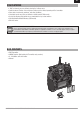
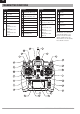
EN Transmitter Functions Function 1 Antenna 2 Speaker Grill 3 Switch H 4 Switch G Function Elevator Trim (Mode 2, 4) 7 Throttle Trim (Mode 1, 3) Aileron Trim (Mode 1,2) 8 Rudder Trim (Mode 3,4) 5 Switch F 6 Throttle/Aileron Stick (Mode 1) Elevator/Aileron Stick (Mode 2) Throttle/Rudder Stick (Mode 3) Elevator/Rudder Stick (Mode 4) 9 Scroll wheel 10 Right Side Grip 11 On/Off Switch 12 LCD 13 Clear Button 14 Back Button 15 SD Card Opening Function Function 16 left Side Grip 21
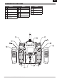
EN Transmitter Functions 6 D C Function 1 2 3 Function Handle Throttle Spring Tension Adjustment (Mode 2,4) Gimbal Stick Tension Adjustment 4 Mode Change 5 Left Rear Grip F Function Gimbal Stick Tension Adjustment 6 Audio Jack 11 7 Charge Port For use with optional Lithium Ion Battery 12 Mode Change 8 Battery Cover 13 9 Trainer Port Throttle Spring Tension Adjustment (Mode 1,3) 10 Right Rear Grip 13 2 1 3 12 4 11 5 10 9 7 6 8 SPEKTRUM DX6 • TRANSMITTER INSTRUCTION M
EN Main Screen Function A Model Name B DSMX/DSM2 If not shown, this indicates “not bound”. C D E F G H Also displays the Volume Level Transmitter Battery when the BACK button is pressed Charge Level Digital Battery Voltage (an alarm sounds and the screen flashes when battery charge gets down to 4.3V when using Alkaline Batteries or 6.4V for a LiPo/Li Ion battery.
EN SD Card Installing the SD Card The SD Card (not included) enables you to: • Import (copy) models from another DX6 transmitter • Export (transfer) models to another DX6 transmitter • Update AirWare™ software in the transmitter • Install/Update sound files To install the SD Card: 1. Power off the transmitter. 2. Press the SD Card into the card slot with the card label facing the back of the transmitter. The card is keyed to fit in the case in only 1 direction. Do not use excessive force to install.
EN Binding F Binding is the process of programming the receiver to recognize the GUID (Globally Unique Identifier) code of a single specific transmitter. You must bind the AR610 receiver to your transmitter before it will operate.
EN Receiver Power System Requirements Inadequate power systems that do not provide the necessary minimum voltage to the receiver during flight have become the number one cause of in-flight failures.
EN Programming Failsafe Positions You establish failsafe positions when you bind your transmitter and receiver. If the radio signal connection is lost between the transmitter and receiver, the receiver immediately moves the aircraft control surfaces to the failsafe positions. If you assign the receiver THRO channel to a transmitter channel other than throttle, we recommend using Preset failsafe with the throttle in the low position.
Throttle Curve Spoken Flight Mode EN Flap System Channel Assign Mixing Trim Setup Range Test Model Utilities Timer Warnings Telemetry Telemetry Menu options show up on model type selection. These menu options vary between Model Types (Airplane, Helicopter and Sailplane), but Custom Voice Setup Preflight are identical for all models in that type. Subsequent aircraft type (Aircraft, SwashplateSetup or Sailplane) selections make other menu options System Setup Frame Rate appear.
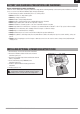
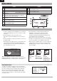
EN System Setup Press and hold the scroll wheel while powering on the transmitter to show the System Setup list. No radio transmission occurs when a System Setup screen is displayed, preventing accidental damage to linkages and servos during changes to programming. F D C 6-CHA CLE NNEL DSMX ® TEL Y SY EMETR STEM AR BAC K 3 MO DEL TYPE eless S Wir Traine ICE r VO TS ALER You can also enter the System Setup from the Function list without turning the transmitter off.
EN System Setup Model Name Model Name enables you to assign a custom name to the current model memory. Model names can include up to 20 characters, including spaces. To add letters to a Model Name: 1. Scroll to the desired letter position and press the scroll wheel once. A flashing box appears. 2. Scroll left or right until the desired character appears. Press the scroll wheel once to save the character. 3. Scroll to the next desired letter position.
EN System Setup Spoken Flight Mode Setup Enables you to assign custom names to the Flight Mode positions. Flight Mode names can include up to 20 characters, including spaces. To change the Flight Mode name: 1. Scroll to the Flight Mode name you wish to change and press the scroll wheel. 2. Scroll to the character position you wish to change and press the scroll wheel once. A flashing box appears. 3. Scroll left or right until the desired character appears.
EN System Setup Trim Setup Use the Trim Setup screen to change the size of the trim step and the trim type. Trim Step Adjusting the trim step value determines how many “clicks” of trim you input each time you press the trim button. Changing the trim step value to 0 disables the trim for the channel. To change the trim step value: 1. Scroll to the trim step channel you wish to change. 2. Select the trim step value and scroll left or right to change the value. 3.
EN System Setup Delete Model Use this selection to permanently delete a model from the model select list. If you do not wish to delete a model, select Cancel to exit the page. 1. To delete a model, highlight the model listed. Press to select then roll to the model name. Press the scroll wheel to select. 2. Select DELETE to delete the model. Copy Model The Model Copy menu enables you to duplicate model programming from one Model List location to another.
EN System Setup Warnings The Warnings menu enables you to program a tone or vibration alert during power on of the transmitter for any selected switch or channel position. The alarm activates and an alert message appears on the screen if a specific switch or control stick is in an unsafe position when you power the transmitter on. Return the switch or control stick to the safe position to silence the alarm.
EN System Setup Telemetry Alarms Select Inh under Alarm to select the type of alarm desired. Options include Inh, Tone, Voice. Status Reports (Spoken Telemetry) 1. Select Inh next to Status Reports in each telemetry setting to add spoken telemetry feedback as desired. 2. Scroll to select how often you want to hear the status report. Warning Reports (Spoken Telemetry) 1. Select Inh next to Warning Reports in each telemetry setting to add spoken telemetry feedback for telemetry warnings as desired. 2.
EN System Setup TRAINER The DX6 features a programmable trainer function with 4 wired trainer modes and 2 wireless trainer modes. The transmitter assigns the trainer function to Switch I. Wired Trainer The 4 wired trainer modes include: Inhibit In Inhibit, the slave transmitter must have the same programming as the master transmitter (e.g., servo reversing, travel adjust, sub-trim, trims).
EN System Setup Wireless Trainer Wireless Trainer works just like the Wired Trainer, without the wire. Select Wireless Trainer to bind a DSM2 or DSMX slave transmitter to the master transmitter. With this option, when the master presses the trainer button or switch, control is given to the currently bound slave transmitter.
EN EN System Setup SYSTEM SETTINGS The System Settings menu consists of four screens: System Settings, Extra Settings, Serial Number and Calibrate. Select NEXT or PREV to move between screens. User Name The User Name field displays your name in the lower right corner of the main screen. To Program a User Name: 1. Scroll to User Name and press the scroll wheel. The User Name screen appears. Contrast 2. Scroll to the desired character position and press the scroll wheel.
EN System Setup Selecting a Language In the Systems Settings screen, scroll to highlight Language, then press the scroll wheel to select the Language function. Scroll to select the desired Language. When the desired Language is selected, press the scroll wheel to accept that Language. Names you input will not be affected by language change. After changing the language for the text, you may also want to change the language for the spoken alerts. See the “Spoken” and “SD Card” sections for more information.
EN System Setup Serial Number The Serial Number screen displays the transmitter serial number and AirWare software version. Reference the Serial Number screen any time you need to register your transmitter or update the AirWare software from the Spektrum Community website. Exporting the Serial Number to the SD Card You may find it helpful to export the transmitter serial number to a text file for your personal records or when you are registering the transmitter on the Spektrum Community.
EN System Setup Transfer SD card The SD Card enables you to: • Import (copy) models from another DX6 transmitter • Export (transfer) models to another DX6 transmitter Import Model This function overwrites all model memories. Ensure that the models currently in your transmitter are saved on an SD card separate from the transmitter before performing this function. To import an individual model file from the SD Card: 1. Save the model file to the SD Card. 2.
EN System Setup Updating Spektrum DX6 Sound Files NOTICE: NEVER disconnect the battery from the transmitter while the file transfer is in process. Doing so will damage the transmitter, and the transmitter will need to be returned for service. You have the option of installing new sound files in the DX6 transmitter. Before updating the sound files, make sure the transmitter battery is fully charged. To install new sound files: 1. Download the desired sound file from the Spektrum Community at www.SpektrumRC.
EN function list The Main Screen appears when you power on the transmitter. Press the scroll wheel once to display the Function List. Press Servo Setup The Servo Setup menu contains the following functions: • Travel Adjust • Sub-Trim • Reverse Travel Adjust Travel Adjust sets the overall travel or endpoints of the servo arm movement. To adjust travel values: 1. Scroll to the channel you wish to adjust and press the scroll wheel. When adjusting travel values assigned to a control stick: a.
EN function list D/R & Exponential Dual Rates and Exponential are available on the aileron, elevator and rudder channels. To adjust the Dual Rate and Exponential: 1. Scroll to the channel and press the scroll wheel once. Scroll left or right to select the channel you wish to change and press the scroll wheel again to save the selection. 2. Scroll to dual rate and press the scroll wheel. Scroll left or right to change the value and press the scroll wheel again to save the selection.
EN function list The following menu options are only available when they are enabled from the Model Type screen. V-Tail DifferentialOnly available in Sailplane Type when V-Tail A or V-Tail B is active. See SAIL (Sailplane) section for set up. Camber Preset Only available in Sailplane Type when a 2 aileron wing type is selected. See SAIL (Sailplane) section for set up. Camber System Only available in Sailplane Type when a 2 aileron wing type is selected. See SAIL (Sailplane) section for set up.
EN function list Back Mixing Back Mixing applies a mix to all related servos in a wing or tail type. For example, if you select 2 AIL, 2 FLAP in the Aircraft Type screen, a mix to one aileron channel affects both aileron servos. The mix response, however, depends on the aileron channel included in the mix. A Back Mix also enables you to use fewer mixes to achieve the desired response, for example adding roll to a split elevator. Range Test The Range Test function reduces the power output.
EN function list Telemetry Telemetry is in both the system setup and the function list so you can access the telemetry functions from either list. You must power off the receiver and transmitter, then power them both on to reset the telemetry data. You can reset min/max values by pressing the CLEAR button. NEVER change Telemetry settings when the aircraft is powered on. There is a brief interruption in RF output when exiting the Telemetry screen, and may cause a “Hold” condition.
EN function list System Setup Use System Setup to enter the System List from the Function list without turning the transmitter off. A Caution screen will appear that warns that RF will be disabled (the transmitter will no longer transmit). Press YES if you are sure and want to access the System List. If you are not sure, press NO to exit to the main screen and continue operation.
EN ACRO (Airplane) Acro Model Type NOTICE: Refer to your airplane manual for recommended control throws. CAUTION: Always do a Control Test of your model with the transmitter after programming to make sure your model responds as desired. Aircraft Type Use the Aircraft Type Screen to select wing and tail types to match your airplane model. Diagrams and setup names show on the transmitter screen to show the available setups. Refer to spektrumrc.
EN ACRO (Airplane) Elevon Servo Control The possible servo reversing options for a delta wing model are: Aileron Normal Normal Reverse Reverse Elevator Reverse Normal Reverse Normal Tip: If you test all servo reversing options and the control surfaces do not move in the correct direction, change the Elevon wing type in the System Setup list from Elevon-A to Elevon-B.
EN HELI (Helicopter) Heli Model Type NOTICE: Refer to your helicopter, gyro and governor manuals for programming recommendations. CAUTION: Always do a Control Test of your model with the transmitter after programming changes to make sure your model responds as desired. Swash Type The Swash Type menu option assigns the swash type for your particular helicopter model. Select the Swash Type before completing any programming in the Function List.
EN HELI (Helicopter) Swashplate The Swashplate menu option enables you to adjust the following: • Swashplate Mix • Exponential • E-Ring • Elevator Compensation Use positive or negative Swashplate mix values as needed for correct direction response of the helicopter. Before making adjustments to the Swashplate mix, make sure the throttle/collective pitch input moves the entire swashplate up or down. If the servos are not moving in the same direction, reverse them as necessary in the Servo Setup menu option.
EN sail (sailplane) Sailplane Model Type NOTICE: Refer to your sailplane manual for recommended control throws. CAUTION: Always do a Control Test of your model with the transmitter after programming to make sure your model responds as desired. Sailplane Type Use the Sailplane Type Screen to select wing and tail types to match your sailplane model. Diagrams and setup names show on the transmitter screen to show the available setups. Refer to spektrumrc.
EN sail (sailplane) SAIL Mixing For each of these mixes, you can program each flight mode with different mix values or at 0% if no mix is desired for that specific flight mode. Programming values include independent control of the direction and amount a slave surface moves in relationship to the master surface. Aileron to Rudder The Aileron to Rudder mix is commonly used for coordinated turns.
EN Physical Transmitter Adjustments Transmitter Mode Conversion You can change transmitter modes among Modes 1, 2, 3 and 4. This conversion requires both a programming and a mechanical change. Programming Conversion: 1. Access the System Settings menu from the Setup List and select the desired Mode. If you are changing between Modes 2/4 or 1/3, you can STOP after Step 1. 2. Exit the System Settings menu to save the selection. 3. Power off the transmitter and remove the transmitter battery pack.
EN Physical Transmitter Adjustments Adjusting the Elevator Centering Screw When changing between Modes 1 and 2, or between Modes 3 and 4, you must adjust the elevator centering screw. 1. Hold the Elevator or Throttle stick in the full up or full down position when you are adjusting the elevator centering screw. Holding the gimbal stick reduces the load on the elevator centering mechanism and makes it easier to adjust the centering screw. 2.
EN Physical Transmitter Adjustments Adjust Stick Tension Adjust stick tension using the screws on the stick gimbals through holes in the back of the transmitter. 1. Pull up the top of the rear grip on the back of the transmitter to adjust the stick gimbal tension. Only the top of the grip must be pulled up to access the adjustment screw. The entire grip does not need to be removed. 2.
EN Troubleshooting Guide Problem Aircraft will not Bind (during binding) to transmitter Aircraft will not link (after binding) to transmitter Possible Cause Solution Transmitter too near aircraft during binding process Move powered transmitter a few feet from aircraft, disconnect and reconnect flight battery to aircraft Aircraft or transmitter is too close to large metal object Move the aircraft or transmitter away from the large metal object The bind plug is not installed correctly in the bind po
EN 1-Year Limited Warranty What this Warranty Covers Horizon Hobby, LLC, (Horizon) warrants to the original purchaser that the product purchased (the “Product”) will be free from defects in materials and workmanship for a period of 1 years from the date of purchase.
EN Warranty and Service Contact Information Country of Purchase United States of America Horizon Hobby Contact Information Horizon Service Center (Repairs and Repair Requests) servicecenter.horizonhobby.com/ RequestForm/ Horizon Product Support (Product Technical Assistance) www.quickbase.com/db/ bghj7ey8c?a=GenNewRecord Heli 888-959-2304 Address 4105 Fieldstone Rd Champaign, Illinois, 61822 USA Air 888-959-2305 sales@horizonhobby.
EN Compliance Information for the European Union AT EE IE PL IS BE BG ES FI IT LT PT RO LI NO CZ CY DE DK FR GR HR HU LU LV MT NL SE SI SK UK CH Instructions for disposal of WEEE by users in the European Union Declaration of Conformity (in accordance with ISO/IEC 17050-1) No.
SPEKTRUM DX6 • TRANSMITTER INSTRUCTION MANUAL 223
© 2014 Horizon Hobby, LLC DSM, DSM2, DSMX, the DSMX logo, Bind-N-Fly, the BNF logo, AirWare, ModelMatch, QuickConnect, SmartSafe, Hangar 9 and the Horizon Hobby logo are trademarks or registered trademarks of Horizon Hobby, LLC. The Spektrum trademark is used with permission of Bachmann Industries, Inc. The SD Logo is a trademark of SD-3C, LLC US 7,391,320. Other patents pending. www.spektrumrc.com Created 6/14 • 43911.