8 Instruction Manual Bedienungsanleitung Manuel d’utilisation Manuale di Istruzioni ® 8e ®
EN NOTICE All instructions, warranties and other collateral documents are subject to change at the sole discretion of Horizon Hobby, LLC. For up-todate product literature, visit horizonhobby.com and click on the support tab for this product.
EN BATTERY AND CHARGING PRECAUTIONS AND WARNINGS Failure to exercise caution while using this product and comply with the following warnings could result in product malfunction, electrical issues, excessive heat, FIRE, and ultimately injury and property damage.
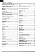
EN TABLE OF CONTENTS Battery and Charging Precautions and Warnings .....................3 Box Contents ..................................................................................3 Installing the Transmitter Batteries .............................................5 Installing Optional Lithium Ion Battery Pack ..............................5 Charging the Lithium Ion Battery Pack .......................................5 Transmitter Functions ..............................................................
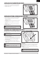
EN INSTALLING THE TRANSMITTER BATTERIES 1. Remove the battery cover from the back of the transmitter. 2. Install the included 4 AA batteries into the battery holder. 3. Install the battery cover. INSTALLING OPTIONAL LITHIUM ION BATTERY PACK 1. Remove the battery cover from the back of the transmitter. 2. Remove the AA battery holder and disconnect from the transmitter power port. 3. Remove the rectangular foam and flat foam from the battery compartment. 4.
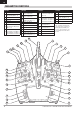
EN TRANSMITTER FUNCTIONS Function 1 LED Elevator Trim (Mode 2, 4) 2 Throttle Trim (Mode 1, 3) 3 R Knob 4 Switch H 5 Switch G 6 Switch F 7 Throttle Tension Adjustment Throttle Ratchet Adjustment (Mode 1, 3) 8 Throttle/Aileron Stick (Mode 1) Elevator/Aileron Stick (Mode 2) Throttle/Rudder Stick (Mode 3) Elevator/Rudder Stick (Mode 4) Function Left/Right Gimbal Stick 9 Tension Adjustment Up/Down Gimbal Stick 10 Tension Adjustment Aileron Trim (Mode 1, 2) 11 Rudder Trim (Mode 3, 4) 12 Neck Strap Mount 13 S
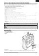
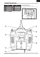
EN TRANSMITTER FUNCTIONS Function 1 Bind Button 2 Switch A 3 Handle 4 5 Mode Change Slider SD Card Opening 6 Function Charge Port for Use w/ Optional Lithium Ion Battery 7 Battery Cover 8 Mode Change Door 9 Antenna Rotation Tension Powering the DX8e On and Off 1. Press the power button to turn on the DX8e. 2. Press and hold the power button for about 4 seconds to power off the DX8e.
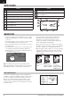
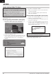
EN MAIN SCREEN Function A Model Name B DSMX/DSM2 If not shown, this indicates not bound C Displays throttle position D Digital Battery Voltage (an alarm sounds and the screen flashes when battery charge gets down to 6.4V for a LiPo/Li Ion battery.
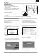
EN SD CARD Installing an SD Card An SD Card (not included) enables you to: • Import (copy) models from any compatible* Spektrum AirWare™ transmitter • Export (transfer) models to any Spektrum AirWare transmitter* • Update Spektrum AirWare software in the transmitter • Install/Update sound files • Back up models for safe keeping To install or remove a SD Card: 1. Power off the transmitter. 2. Remove the battery door. 3. Press the SD Card into the card slot with the card label facing up as shown.
EN SD CARD Update Spektrum AirWare™ Software NOTICE: The orange LED Spektrum bars flash and a status bar appears on the screen when Spektrum AirWare software updates are installing. Never power off the transmitter when updates are installing. Doing so may damage the system files. NOTICE: Before installing any Spektrum AirWare files, always Export All Models to an SD Card separate from the SD Card containing the update. The update may erase all model files.
EN BINDING Binding is the process of programming the receiver to recognize the GUID (Globally Unique Identifier) code of a single specific transmitter. You must bind the receiver to your transmitter before it will operate. Binding Using the Receiver and Receiver Battery 1 2 3 4 5 6 1. Lower throttle to the lowest position and make sure the transmitter is powered off. 2. Insert the bind plug into the BIND/DATA port. 3. Insert the receiver battery into ANY open port.
EN RECEIVER POWER SYSTEM REQUIREMENTS Inadequate power systems that do not provide the necessary minimum voltage to the receiver during flight have become the number one cause of in-flight failures. Some of the power system components that affect the ability to properly deliver adequate power include: • Receiver battery pack (number of cells, capacity, cell type, state of charge) The AR8010T has a minimum operational voltage of 3.5 volts; test the power system per the guidelines below.
EN PROGRAMMING FAILSAFE POSITIONS You establish failsafe positions when you bind your transmitter and receiver. If the radio signal connection is lost between the transmitter and receiver, the receiver immediately moves the aircraft control surfaces to the failsafe positions. If you assign the receiver THRO channel to a transmitter channel other than throttle, we recommend using Preset failsafe with the throttle in the low position. NOTICE: Failsafe features vary according to receiver.
EN MODEL TYPE PROGRAMMING GUIDE Menu options show up on model type selection. These menu options vary between Model Types (Airplane, Helicopter,Sailplane and Multirotor), but are identical for all models in that type. Subsequent aircraft type (Aircraft, Swashplate,Sailplane or Multirotor) selections make other menu options appear.
EN SYSTEM SETUP Press and hold the scroll wheel while powering on the transmitter to show the System Setup list. No radio transmission occurs when a System Setup screen is displayed, preventing accidental damage to linkages and servos during changes to programming. You can also enter the System Setup from the Function list without turning the transmitter off. A Caution screen will appear that warns that RF will be disabled (the transmitter will no longer transmit).
EN SYSTEM SETUP Model Name Model Name enables you to assign a custom name to the current model memory. Model names can include up to 20 characters, including spaces. To add letters to a Model Name: 1. Scroll to the desired letter position and press the scroll wheel once. A flashing box appears. 2. Scroll left or right until the desired character appears. Press the scroll wheel once to save the character. 3. Scroll to the next desired letter position. Repeat Steps 1 and 2 until the Model Name is complete.
EN SYSTEM SETUP Flight Mode Setup Enables you to assign custom names to the Flight Mode positions. Flight Mode names can include up to 20 characters, including spaces. To change the Flight Mode name: 1. Scroll to the Flight Mode name you wish to change and press the scroll wheel. 2. Scroll to the character position you wish to change and press the scroll wheel once. A flashing box appears. 3. Scroll left or right until the desired character appears. Press the scroll wheel once to save the character.
EN SYSTEM SETUP Trim Setup Use the Trim Setup screen to change the size of the trim step and the trim type. Trim Step Adjusting the trim step value determines how many “clicks” of trim you input each time you press the trim button. Changing the trim step value to 0 disables the trim for the channel. To change the trim step value: 1. Scroll to the trim step channel you wish to change. 2. Select the trim step value and scroll left or right to change the value. 3. Press the scroll wheel to save the selection.
EN SYSTEM SETUP 4Copy Model The Model Copy menu enables you to duplicate model programming from one Model List location to another. Use Model Copy to: • Save a default model copy before experimenting with programming values • Expedite programming for a model using a similar programming setup IMPORTANT: Copying a model program from one model memory to another will erase any programming in the “To” model memory. To copy model programming: 1. Make sure the model program you wish to copy is active.
EN SYSTEM SETUP TELEMETRY Installing the optional telemetry module and sensors enables the display of aircraft performance data on the transmitter screen. You can also enable Data Logging to save a telemetry file on the SD Card and view the data in the Spektrum STiTM mobile application. 4Telemetry Settings Display Telemetry display options include: Tele: When you press the scroll wheel, the Telemetry screens appear and the Main Screen is disabled.
EN SYSTEM SETUP 4Telemetry Alarms Select Inh under Alarm to select the type of alarm desired. Options include Inh and Tone. File Settings This is used to select the data logging settings. File Name 1. Select File Name to assign a custom file name. 2. The File Name screen appears, allowing you to name the file as you would for a Model Name or Flight Mode Name. The file name can include a maximum of 8 characters. 3. Press BACK to save the name. Enabled When Enabled is set to NO, Data Logging is turned off.
EN SYSTEM SETUP 4Wireless Trainer Wireless Trainer works just like the Wired Trainer, without the wire. Select Wireless Trainer to bind a DSM2 or DSMX slave transmitter to the master transmitter. With this option, when the master presses the trainer button or switch, control is given to the currently bound slave transmitter.
EN SYSTEM SETUP 4Trainer FPV Mode The Trainer FPV function enables you to control FPV head-tracking in wireless mode. You may assign incoming head-tracker channels to any available output channel in the transmitter. To use the FPV mode: 1. Change the trainer mode from Inhibit to FPV. 2. Select the switch you wish to use for the head tracker, then select NEXT. 3. Select the Output Channel where the head tracker servo is connected. 4. Change Mode: Master to Mode: Slave. 5. Select Input Channel. 6.
EN SYSTEM SETUP SYSTEM SETTINGS The System Settings menu consists of four screens: System Settings, Extra Settings, Serial Number and Calibrate. Select NEXT or PREV to move between screens. 4User Name The User Name field displays your name in the lower right corner of the main screen. To Program a User Name: 1. Scroll to User Name and press the scroll wheel. The User Name screen appears. 2. Scroll to the desired character position and press the scroll wheel.
EN SYSTEM SETUP 4Selecting a Language In the Systems Settings screen, scroll to highlight Language, then press the scroll wheel to select the Language function. Scroll to select the desired Language. When the desired Language is selected, press the scroll wheel to accept that Language. Names you input will not be affected by language change. After changing the language for the text, you may also want to change the language for the spoken alerts. See the “Spoken” and “SD Card” sections for more information.
EN SYSTEM SETUP 44Serial Number The Serial Number screen displays the transmitter serial number and Spektrum AirWare software version. Reference the Serial Number screen any time you need to register your transmitter or update the Spektrum AirWare software from the Spektrum Community website.
EN SYSTEM SETUP Transfer SD Card The SD Card enables you to: • Import (copy) models from another DX8e transmitter • Export (transfer) models to another DX8e transmitter • Update Spektrum AirWare™ software in the transmitter • Install/Update sound files 4Import Model This function overwrites all model memories. Ensure that the models currently in your transmitter are saved on an SD card separate from the transmitter before performing this function. To import an individual model file from the SD Card: 1.
EN SYSTEM SETUP 4Update AirWare Software NOTICE: The orange LED Spektrum bars flash and a status bar appears on the screen when AirWare software updates are installing. Never power off the transmitter when updates are installing. Doing so may damage the system files. Before installing any AirWare files, always Export All Models to an SD Card separate from the SD Card containing the update. The update may erase all model files. For more information on AirWare software updates, visit spektrumrc.
EN FUNCTION LIST The Main Screen appears when you power on the transmitter. Press the scroll wheel once to display the Function List. Servo Setup The Servo Setup menu contains the following functions: • Travel Adjust • Sub-Trim • Reverse • Speed • Balance 4Travel Adjust Travel Adjust sets the overall travel or endpoints of the servo arm movement. To adjust travel values: 1. Scroll to the channel you wish to adjust and press the scroll wheel.
EN FUNCTION LIST 4Speed The Speed menu enables you to slow the response time on any individual channel (such as retracts). The Speed is adjustable in the following ranges: • Nor (No Delay) – 0.9s in 0.1 second increments • 1s – 2s in 0.2-second increments • 2s – 8s in 1-second increments To adjust the Speed: 1. Scroll to the channel you wish to adjust and press the scroll wheel. 2. Scroll left or right to adjust the speed and press the scroll wheel to save the selection.
EN FUNCTION LIST 4D/R & Exponential Dual Rates and Exponential are available on the aileron, elevator and rudder channels. To adjust the Dual Rate and Exponential: 1. Scroll to the channel and press the scroll wheel once. Scroll left or right to select the channel you wish to change and press the scroll wheel again to save the selection. 2. Scroll to Switch and select the switch to activate D/R and Expo for that channel. 3. Scroll to dual rate and press the scroll wheel.
EN FUNCTION LIST The following menu options are only available when they are enabled from the Model Type screen. V-Tail Differential4Only available in Sailplane Type when V-Tail A or V-Tail B is active. See SAIL (Sailplane) section for set up. Camber Preset 4Only available in Sailplane Type when a 2+ aileron wing type is selected. See SAIL (Sailplane) section for set up. Camber System 4Only available in Sailplane Type when a 2+ aileron wing type is selected. See SAIL (Sailplane) section for set up.
EN FUNCTION LIST Back Mixing Back Mixing applies to all related servos in a multi servo Aileron/ Flapped wing or a multi servo split elevator. Creating a mix to RAL (Right Aileron) or LAL (Left Aileron) will create different results and enables you to use fewer mixes to achieve the desired response. Example 1: Creating a mix AIL > RAL will move the ailerons in opposite directions, while creating a mix AIL > LAL will move the ailerons in the same direction.
EN FUNCTION LIST 4Timer Event and Timer Control Alerts Press NEXT to select the Timer Event Alerts settings. These include options for the alerts at every minute for down timers, 1 minute remaining alert, 30 seconds remaining alert, 10 second to 1 second remining alerts, expiration alert, and every minute up alert. Press NEXT again to select the Timer Control Alerts settings. Available options include Timer Start alert, Timer Stop alert, and Timer Reset alert.
EN ACRO (AIRPLANE) Acro Model Type NOTICE: Refer to your airplane manual for recommended control throws. CAUTION: Always do a Control Test of your model with the transmitter after programming to make sure your model responds as desired. Aircraft Type Use the Aircraft Type Screen to select wing and tail types to match your airplane model. Diagrams and setup names show on the transmitter screen to show the available setups. Refer to spektrumrc.
EN ACRO (AIRPLANE) Elevon Servo Control The possible servo reversing options for a delta wing model are: Aileron Normal Normal Reverse Reverse Elevator Reverse Normal Reverse Normal Tip: If you test all servo reversing options and the control surfaces do not move in the correct direction, change the Elevon wing type in the System Setup list from Elevon A to Elevon B.
EN HELI (HELICOPTER) Heli Model Type NOTICE: Refer to your helicopter, gyro and governor manuals for programming recommendations. CAUTION: Always do a Control Test of your model with the transmitter after programming changes to make sure your model responds as desired. To change the Helicopter Icon: From the Collective Type Screen, select NEXT at the bottom right of the screen. This will access the Heli image screen. Scroll to the icon and click once.
EN HELI (HELICOPTER) Swashplate The Swashplate menu option enables you to adjust the following: • Swashplate Mix • Exponential • E-Ring • Elevator Compensation Use positive or negative Swashplate mix values as needed for correct direction response of the helicopter. Before making adjustments to the Swashplate mix, make sure the throttle/collective pitch input moves the entire swashplate up or down. If the servos are not moving in the same direction, reverse them as necessary in the Servo Setup menu option.
EN SAIL (SAILPLANE) Sailplane Model Type NOTICE: Refer to your sailplane manual for recommended control throws. CAUTION: Always do a Control Test of your model with the transmitter after programming to make sure your model responds as desired. Sailplane Type Use the Sailplane Type Screen to select wing and tail types to match your sailplane model. Diagrams and setup names show on the transmitter screen to show the available setups. Refer to spektrumrc.
EN SAIL (SAILPLANE) SAIL Mixing For each of these mixes, you can program each flight mode with different mix values or at 0% if no mix is desired for that specific flight mode. Programming values include independent control of the direction and amount a slave surface moves in relationship to the master surface. Aileron to Rudder The Aileron to Rudder mix is commonly used for coordinated turns.