® ® 2-Channel, 2-Model Memory DSM Racing System
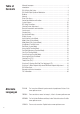
Table of Contents Alternate Languages................................................................................................ 2 Introduction............................................................................................................ 3 DX2.0 Quick Start Setup......................................................................................... 3 DX2.0 with Digital Spectrum Modulation................................................................ 5 Binding.........................
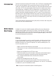
Introduction Thank you for purchasing Spectrum’s DX2.0 radio system. The DX2.0 is designed to provide R/C racers with a bulletproof 2.4GHz spread spectrum radio link. With the DX2.0 DSM system you’ll no longer have to wait for a frequency clip, worry about radio interference from noisy motors or ESCs or be concerned that someone may turn on a radio on your channel causing interference. In addition, the DX2.
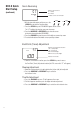
Servo Reversing st – – DX2.0 Quick Start Setup (continued) REV • NORM Indicates Current Channel ST = Steering TH = Throttle Indicates Current Servo Direction ENter CLEAR INCREASE DECREASE SCROLL Channel 1. With the transmitter power switch on, press the SCROLL key to enter the Function mode. 2. Press the SCROLL key until “REV.NORM” appears on the screen. The “ST” indicates the steering servo reversing screen. 3.
DX2.0 with Digital Spectrum Modulation The DSM® system operates in the 2.4GHz band (that’s 2400MHz). This high frequency offers a significant advantage as it’s well out of the range of model-generated radio interference (like motor and ESC noise). All the complex issues that now exist using 27 and 75MHz radios with model-generated interfering noise are eliminated with this system. The DSM system uses Direct Sequencing Spread Spectrum modulation to generate a wide signal on a single frequency.
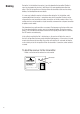
Binding During the first installation, the receiver(s) must be bound to the transmitter. Binding is necessary to program the receiver(s) to distinguish its corresponding transmitter from others. Also fail-safe positions are transferred from the transmitter to the receiver during binding. See binding below for more details. It is necessary to bind the receiver to the transmitter during the first installation, and is recommended when the receiver is moved from one vehicle to another.
Binding (continued) 2. With the receiver off, press and hold the bind button on the receiver while turning on the receiver. 3. Release the bind button when the LED flashes green. 4. With the transmitter off, place the transmitter steering wheel and throttle trigger channels in their desired fail-safe positions (normally brake and straightahead steering). LED and Bind Button 5. Press and hold the bind button on the transmitter while turning on the transmitter. 6.
Steering and Throttle Trim Adjustment TRIM STC – Direct Trim Access 0 TRIM THC 0 E P A R/B BRK 50 Indicates Steering Trim Function Indicates Current Value Indicates Throttle Trim Function Indicates Current Value Brake Function Indicates Current Value Steering Servo Trim Adjustment: 1. With the transmitter power switch on, move the digital steering trim lever in the desired position to be adjusted. The steering trim value screen will appear automatically. Throttle Servo Trim Adjustment: 2.
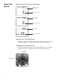
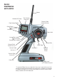
Control Identification and Location Antenna Multidata LCD Display Three Character Name Input Electronic Digital Steering Trim Lever Digital Voltage Reading Channel Button Enter Function Scroll Button Power Switch Increase Button Clear Function Decrease Button Steering Wheel Electronic Digital Throttle Trim Lever Throttle Trigger Electronic Digital Grip Lever A Grip Button C Adjustable Steering Tension Electronic Digital Grip Lever B Charge Jack Battery cover * (8 “AA” Batteries Required * To rem
System Features • DSM 2.
Receiver Connections and Installation Note: When using a separate Ni-Cd receiver as a power source, the operating voltage range is 4.8–6.0V (4–5 cells) under load. Attention: Make sure the male and female connectors have the correct polarity (+/–) before connecting. Be sure to orient the servo plug correctly for proper insertion. Most electronic speed controllers are set up for B.E.C. (Battery Elimination Circuitry) operation and plug directly into your receiver.
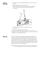
Servo Layout Note: Rubber grommets (and sometimes eyelets) are used in fuelpowered vehicles. 4FSWP .PVOUJOH 'MBOHF 4FSWP "SN 3FUBJOJOH 4DSFX 4FSWP "SN )PSO 4FSWP 0VUQVU 4IBGU 3VCCFU (SPNNFUT 4FSWP $BTF 4FSWP &ZFMFU 4FSWP -FBE X $POOFDUPS 4FSWP .PVOUJOH 'MBOHF 3VCCFU (SPNNFUT 4OP 6IEW Charging Jack Located on the left-hand side of the transmitter is the charging jack, which accepts only JR® or Spektrum® style wall chargers.
Display Screens Normal Display Screen When the power switch is turned on, the LCD screen will read as shown below. This screen is referred to as the Normal Display. Note: If any of the electronic trim buttons are moved while in this screen, the screen will automatically change to display the trim in use. This is called the Direct Trim Mode. For more information on the feature, please see page 8 of this manual. -- MD1 10.
Accessing the System Mode To enter the System Mode, press both the SCROLL and CHANNEL keys at the same time while turning on the transmitter power switch. By pressing the SCROLL key, you can now choose Model Select, Model Name Input, Grip Button C function or the Data Reset function as shown here on the System Mode flow chart. Information for each function is located on the page number listed next to the function name on the flow chart.
Model Select (System Mode) The DX2.0 has memory for two models. This feature allows for two different models to be operated with the same transmitter (additional receivers and servos must be purchased separately) or one model with two different race setups. -- MDL I Model Select Function Model Number Accessing the Model Select Function 1. Press the SCROLL and CHANNEL keys at the same time and hold. 2. Turn the transmitter power switch on to enter System Mode. 3.
Model Name Entry (System Mode) The DX2.0 allows a three-character name to be input for each of the two (2) models available. The current model, with name, will then be displayed in the Normal display screen. This feature is useful to help identify different models, setups, etc. For information on selecting models 1 or 2, please refer to the Model Select Function (page 15).
Data Reset (System Mode) The Data Reset function allows you to reset all the programming in the selected model (1 or 2) to the factory default settings. Before using the Data Reset function, it’s important to enter the Model Select function and check to make sure the current model number indicated (1 or 2) is the model to which you want to reset to the factory default settings. The Model Select function is described in detail on page 15.
Accessing the Function Mode Next, press the SCROLL key until a beep is heard. The display will change to show the first function listed on the Function Mode flow chart as shown below. Press the SCROLL key to scroll down through the functions one by one, as shown in the flow chart. Once the desired function has been reached, use the CHANNEL key to select the appropriate channel (if applicable).
End-Point Adjustment (Function Mode) steering and throttle servos to be increased or decreased in each direction to achieve the exact servo movement needed. The End-Point Adjustment range is from 0% to 125% and is factory set to 100% for both channels. The value displayed on the screen depends on the current position of the steering wheel, trigger, or trim lever to be adjusted.
Sub-Trim (Function Mode) The Sub-Trim function of the DX2.0 is an electronic trimming feature that allows the neutral position of the servo on either the steering or throttle channel to be moved, while allowing the electronic trim lever for that channel to remain in the center position. This feature is very useful, as it allows the servo arm/wheel position to be moved to help with control linkage installation, eliminating the need to make mechanical linkage adjustments.
Servo Reversing (Function Mode) The Servo Reversing feature of the DX2.0 is a very convenient feature when setting up a new model. The purpose of the Servo Reversing function is to change the direction of the servo rotation in relation to the wheel/trigger movement. The Servo Reversing function is available for the steering and throttle of the DX2.0. – st – REV • NORM Indicates curent channel: ST = Steering TH = Throttle Indicates current servo direction Accessing the Servo Reversing Function 1.
Accessing the Direct Trim Mode (Function Mode) The Direct Trim Mode function of the DX2.0 is accessible through the use of the electronic throttle or steering trim levers, as well as the two electronic grip levers (A&B) located on the upper portion of the grip handle. This function allows for quick trim adjustment of these controls, without the need to access these functions through the four keypad control keys. To access the Direct Trim Mode function, turn on the transmitter power switch.
Steering Trim (STC) The DX2.0 electronic Steering Trim lever, located just above the steering wheel, allows the center position of the servo to be manipulated in either direction to achieve precise centering of the steering assembly. Steering Travel End-Point Adjustment values (page 19) remain completely independent from the steering trim, unless the trim value exceeds the selected end-point values.
Throttle Trim (THC) The DX2.0’s electronic Throttle Trim lever, located to the left of the steering wheel, allows the center position of the servo to be manipulated in either direction to achieve precise centering of the throttle trigger neutral position. Throttle End-Point adjustment values (page 19) remain completely independent from the throttle trim, unless the trim value exceeds the selected end-point values.
Grip Lever B: Steering Dual Rate Trim Adjustment STG The Steering Dual Rate Trim Adjustment, located at Grip Lever B, allows the dual rate value (maximum servo travel) to be increased or decreased within a range from 100% through 20% of the total end-point value established in the steering EPA function. This function is very useful in race conditions as it allows you to custom tailor the steering radius and sensitivity for the current track conditions.
Grip Lever A: Brake End-Point Adjustment BRK The Brake End-Point Adjustment, located at Grip Lever A, allows the maximum servo travel on the braking side of the throttle trigger to be increased or decreased from 100% to 0% (off). This function is very useful in race conditions as it allows the racer to custom tailor the “panic” brake value to maximize the car’s braking power for the current track conditions.
DX2.0 Data Sheet Use the programming sheet to record the information for the programs in your DX2.0 radio system. Feel free to make copies of this programming sheet.
DX2.0 Data Sheet Use the programming sheet to record the information for the programs in your DX2.0 radio system. Feel free to make copies of this programming sheet.
Warranty and Service Information Spektrum® 1-Year Limited Warranty Period Horizon Hobby, Inc. guarantees this product to be free from defects in both material and workmanship for a period of 1 year from the date of purchase. Limited Warranty & Limits of Liability Pursuant to this Limited Warranty, Horizon Hobby, Inc. will, at its option, (i) repair or (ii) replace, any product determined by Horizon Hobby, Inc. to be defective. In the event of a defect, these are your exclusive remedies.
FCC Information This device complies with part 15 of the FCC rules. Operation is subject to the following two conditions: (1) This device may not cause harmful interference, and (2) this device must accept any interference received, including interference that may cause undesired operation. Caution: Changes or modifications not expressly approved by the party responsible for compliance could void the user’s authority to operate the equipment.
® ® © 2006 Horizon Hobby, Inc. 4105 Fieldstone Road Champaign, Illinois 61822 (877) 504-0233 horizonhobby.