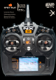
NX8 8 ® Instruction Manual Bedienungsanleitung Manuel d’utilisation Manuale di Istruzioni ®
EN NOTICE All instructions, warranties and other collateral documents are subject to change at the sole discretion of Horizon Hobby, LLC. For up-todate product literature, visit horizonhobby.com or towerhobbies.com and click on the support or resources tab for this product.
EN BATTERY AND CHARGING PRECAUTIONS AND WARNINGS WARNING: Failure to exercise caution while using this product and comply with the following warnings could result in product malfunction, electrical issues, excessive heat, FIRE, and ultimately injury and property damage. • NEVER LEAVE CHARGING BATTERIES UNATTENDED. • NEVER CHARGE BATTERIES OVERNIGHT. • Never attempt to charge dead, damaged or wet battery packs. • Never attempt to charge a battery pack containing different types of batteries.
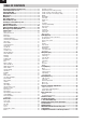
EN TABLE OF CONTENTS Charging the Lithium Ion Battery Pack........................................5 Connecting the USB to a PC..........................................................5 Updating with WiFi.........................................................................5 Transmitter Functions....................................................................6 Main Screen....................................................................................8 Navigation..................................
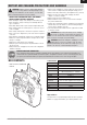
EN CHARGING THE LITHIUM ION BATTERY PACK The NX8 transmitter has an internal charger that is powered from any common Micro USB power supply. CAUTION: Never connect an external battery charger to your NX8 transmitter. Always charge the transmitter on a heat-resistant surface. 1. Power off your transmitter. 2. Connect the power supply to a power outlet using the appropriate adapter. 3. Connect your micro USB cable to the charge port located on the back of the NX8. 4.
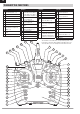
EN TRANSMITTER FUNCTIONS Function Elevator Trim (Mode 2, 4) 1 Throttle Trim (Mode 1, 3) 2 R Trimmer 3 R Knob 4 Switch E 5 Switch H 6 Switch G 7 Switch F 8 Throttle Tension Adjustment Throttle Ratchet Adjustment (Mode 1, 3) Gimbal Travel Limiter Access Panel 10 Mode Change Screw 9 Function Throttle/Aileron Stick (Mode 1) Elevator/Aileron Stick (Mode 2) 11 Throttle/Rudder Stick (Mode 3) Elevator/Rudder Stick (Mode 4) 12 13 14 15 16 17 18 19 20 Left/Right Gimbal Stick Tension Adjustment Up/Down Gimbal Sti
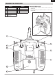
EN TRANSMITTER FUNCTIONS Function Function 1 Switch I/ Bind 7 Data Port 2 Switch A 8 Audio Port 3 Mounting for CSRF 9 Switch H 4 Micro USB Connector 10 Antenna Rotation Tension 5 Memory Card Opening 6 Battery Cover Powering the NX8 On and Off 1. Press and hold the Spektrum Logo for several seconds to turn ON the NX8. 2. Press and hold the power button for about 4 seconds to power OFF the NX8.
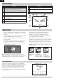
EN MAIN SCREEN Function Function Rudder Trim (Mode 1, 2) Aileron Trim (Mode 3, 4) Throttle Trim (Mode 2, 4) Elevator Trim (Mode 1, 3) A Model Name B DSMX/DSM2 If not shown, this indicates not bound C Displays throttle position D Digital Battery Voltage (an alarm sounds and the screen flashes when battery charge gets down to 3.2V for a Li Ion battery.
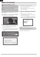
EN EXTERNAL MEMORY CARD Installing an external Memory card A Micro Memory card (not included) enables you to: • Import (copy) models from any compatible* Spektrum AirWare™ transmitter • Export (transfer) models to any Spektrum AirWare transmitter* • Update Spektrum AirWare software in the transmitter • Install/Update sound files • Back up models for safe keeping To install or remove a Memory card: 1. Power OFF the transmitter. 2.
EN MEMORY CARD FUNCTIONS Update Spektrum AirWare™ Software NOTICE: The orange LED Spektrum bars flash and a status bar appears on the screen when Spektrum AirWare software updates are installing. Never power off the transmitter when updates are installing. Doing so may damage the system files. NOTICE: Before installing any Spektrum AirWare files, always Export All Models to an Memory card separate from the Memory card containing the update. The update may erase all model files.
Audio Events Trainer VTX Setup Analog Switch Setup EN Function Bar Digital Switch Setup Start Timer Center Tone System Setup Sound Utilities Monitor System Settings Menu options show up on model type selection. These menu options varyWiFi between Model Types (Airplane, Helicopter,Sailplane and Utilities Multirotor), but are identical for all models in that type. Subsequent aircraft type (Aircraft, Swashplate,Sailplane or Multirotor) selections USB Settings make other menu options appear.
EN SYSTEM SETUP Enter the System Setup menu to define baseline settings for your model such as what type of aircraft, wing type, flight mode setup, etc. The options chosen in the system menu configures the function list for the chosen model number for your requirements. Some options, such as the flap menu, will not appear at all in the function list until they are selected within the System Setup menu. Press and hold the scroll wheel while powering on the transmitter to show the System Setup list.
EN SYSTEM SETUP Model Name Model Name enables you to assign a custom name to the current model memory. Model names can include up to 20 characters, including spaces. To add letters to a Model Name: 1. Scroll to the desired letter position and press the scroll wheel once. A flashing box appears. 2. Scroll left or right until the desired character appears. Press the scroll wheel once to save the character. 3. Scroll to the next desired letter position. Repeat Steps 1 and 2 until the Model Name is complete.
EN SYSTEM SETUP Flight Mode Setup Enables you to assign custom names to the Flight Mode positions. Flight Mode names can include up to 20 characters, including spaces. To change the Flight Mode name: 1. Scroll to the Flight Mode name you wish to change and press the scroll wheel. 2. Scroll to the character position you wish to change and press the scroll wheel once. A flashing box appears. 3. Scroll left or right until the desired character appears. Press the scroll wheel once to save the character.
EN SYSTEM SETUP Trim Setup Use the Trim Setup screen to change the size of the trim step and the trim type. Trim Step Adjusting the trim step value determines how many “clicks” of trim you input each time you press the trim button. Changing the trim step value to 0 disables the trim for the channel. To change the trim step value: 1. Scroll to the trim step channel you wish to change. 2. Select the trim step value and scroll left or right to change the value. 3. Press the scroll wheel to save the selection.
EN SYSTEM SETUP Create New Model Use this selection to create a new model in the model select list. 1. Select Create New Model. Within this screen, you will have the option to create a new model or cancel. 2. Select the model type. Choose the aircraft image to define the model type for a blank model file, or select Template to load a template file. A SAFE template and a SAFE Select template come pre-loaded on your NX8.
EN SYSTEM SETUP Model Reset Use the Model Reset menu to delete all model programming in the active model memory. Reset returns all model settings to the default settings and erases all programming in the selected model. After a model reset, it is necessary to re-bind. Sort Model List With this function you can sort the model order in the model select function. This is helpful to group similar models together to make them easy to find.
EN SYSTEM SETUP TELEMETRY Installing the optional telemetry module and sensors enables the display of aircraft performance data on the transmitter screen. You can also enable Data Logging to save a telemetry file on the Memory card and view the data in the Spektrum STiTM mobile application or other TLM file viewers. Telemetry Settings Display Telemetry display options include: Tele: When you press the scroll wheel, the Telemetry screens appear and the Main Screen is disabled.
EN SYSTEM SETUP Preflight Setup The Preflight Setup menu option enables you to program a pre-flight checklist that appears each time you power on the transmitter or when you select a new model memory. Each item on the list must be confirmed before you can access the Main Screen. Frame Rate The Frame Rate menu enables you to change the frame rate and modulation mode. Select the option you wish to change and press the scroll wheel. You must use digital servos if you select 11ms frame rate.
EN SYSTEM SETUP Wireless Trainer Wireless Trainer works just like the Wired Trainer, without the wire. NX8 Wireless Trainer Operation Select Wireless Trainer to bind a DSM2 or DSMX student transmitter 1. Enter an unused model on the student transmitter (computer to the instructor transmitter. With this option, when the instructor transmitter only). presses the trainer button or switch, control is given to the currently 2. Bind the instructor transmitter to the model. bound student transmitter.
EN SYSTEM SETUP FPV This mode is available for connecting a head tracking system to the NX8 for FPV use. See the Headtracking FPV Setup section for more information. P-Link Student This training mode designates the NX8 as the student transmitter. Use this option if the instructor transmitter is set up with Wired Pilot Link Instructor. A Start Student Mode button appears, which activates and deactivates wired trainer student capabilities.
EN SYSTEM SETUP Palette Utilities The colors on the NX8 may be customized as you wish. Select from the pre-defined color options listed under Global Customized, or select Personalize to create your own RGB color scheme. SYSTEM SETTINGS The System Settings menu consists of four screens: System Settings, Extra Settings, Serial Number and Calibrate. Select NEXT or PREV to move between screens. User Name The User Name field displays your name in the lower right corner of the main screen.
EN SYSTEM SETUP Selecting a Language In the Systems Settings screen, scroll to highlight Language, then press the scroll wheel to select the Language function. Scroll to select the desired Language. When the desired Language is selected, press the scroll wheel to accept that Language. Names you input will not be affected by language change. After changing the language for the text, you may also want to change the language for the spoken alerts.
EN SYSTEM SETUP Trim Style: Trim style changes the shape of the trim indicators on the Main Screen. Display options include: • Boxed Boxes (Default)– The indicators appear as an outlined box when you adjust the trim. • Boxed Arrows– The indicators appear as outlined arrows when you adjust the trim. • Arrows on Lines– The indicators appear as arrows on lines when you adjust the trim. Inhibit removes all trim bars and indicators from the Main Screen. To change the Trim style: 1.
EN SYSTEM SETUP Factory Reset: Select this option to reset the NX8 back to factory settings. Choosing this option will wipe out any settings and all models that have been set in the NX8 programming. Calibrate The Calibration screen stores the potentiometer endpoints for all proportional controls. It is mandatory to complete the calibration after changing the stick mode selection. Calibrating the Transmitter 1. Carefully move the gimbal sticks in a + shape moving from left to right, then up and down.
EN SYSTEM SETUP Transfer Memory card This menu enables you to: • Import (copy) models from another NX8 transmitter • Export (transfer) models to another NX8 transmitter • Update Spektrum AirWare™ software in the transmitter • Install/Update sound files • • • Take screen shots Import or export color palettes Select from internal or external memory locations Memory Location In the Volume selection you can choose from the Internal or Extermal memory locations.
EN SYSTEM SETUP Export Model You can use the Export Model option to export a single model file to the Memory card. 1. Make sure the active model file is the one you wish to Export. 2. In the Transfer Memory card menu, scroll to Options and press the scroll wheel once. 3. Scroll to Export Model and press the scroll wheel again to save the selection. The Export to SD screen appears. The first two characters of the file name correspond to the Model List number (01, for example). 4.
EN SYSTEM SETUP Update AirWare NOTICE: The orange LED Spektrum bars flash and a status bar appears on the screen when AirWare updates are installing. Never power off the transmitter when updates are installing. Doing so may damage the system files. Before installing any AirWare files, always Export All Models to an Memory card separate from the Memory card containing the update. The update may erase all model files. For more information on AirWare updates, visit spektrumrc.
EN FUNCTION LIST Once you have selected the model number you want to use and have defined the aircraft type, wing and tail type and other details in the System Setup menu, use the Function list to define the details specific to your model’s setup such as servo travel, reversing, mixing, etc. The Main Screen appears when you power on the transmitter. Press the scroll wheel once to display the Function List.
EN FUNCTION LIST Speed The Speed menu enables you to slow the response time on any individual channel (such as retracts). The Speed is adjustable in the following ranges: • Nor (No Delay) – 0.9s in 0.1 second increments • 1s – 2s in 0.2-second increments • 2s – 8s in 1-second increments To adjust the Speed: 1. Scroll to the channel you wish to adjust and press the scroll wheel. 2. Scroll left or right to adjust the speed and press the scroll wheel to save the selection. Absolute (Abs.) Travel The Abs.
EN FUNCTION LIST Dual Rates and Expo Dual Rates and Exponential are available on the aileron, elevator and rudder channels. To adjust the Dual Rate and Exponential: 1. Scroll to the channel and press the scroll wheel once. Scroll left or right to select the channel you wish to change and press the scroll wheel again to save the selection. 2. Scroll to Switch and select the switch to activate D/R and Expo for that channel. 3. Scroll to dual rate and press the scroll wheel.
EN FUNCTION LIST The following menu options are only available when they are enabled from the Model Type screen. V-Tail Differential Only available in Sailplane Type when V-Tail A or V-Tail B is active. See SAIL (Sailplane) section for set up. Camber Preset Only available in Sailplane Type when a 2+ aileron wing type is selected. See SAIL (Sailplane) section for set up. Camber System Only available in Sailplane Type when a 2+ aileron wing type is selected. See SAIL (Sailplane) section for set up.
EN FUNCTION LIST Curve Mix If you want to be able to assign the output channel to respond on a curve or act as a switch, the Curve mix option will enable you to move the output channel to any value at up to 7 points along the travel of the input channel. Below the curve values, select a channel for master control on the left and slave on the right. For example, Throttle > Rudder makes Throttle the master channel and Rudder the slave channel.
EN FUNCTION LIST Timer The NX8 Timer function allows you to program a countdown timer or stop watch (count up timer) to display on the main screen. An alarm sounds when the programmed time is reached. You can program the timer to start using the assigned switch position or automatically when throttle is raised above a programmed position. Two internal timers are available that show run time for a specific model displays on the Main Screen. A total system timer is also available.
EN FUNCTION LIST Forward Programming If you Bind a Forward Programming capable receiver to your NX8, a Forward Programming menu will appear in the Function List automatically. Think of the Forward Programming menu as a programming interface for your connected receiver. The menu structure, options and any changes made are done directly on the receiver, the transmitter is only an interface.
EN FUNCTION LIST Sequencer The Sequencer menu option provides this-then-that mixing with a time delay. Two sequences are available to control two functions each (A and B), in 2 timing directions (forward or reverse). Sequences appear throughout function screens as assignable switches. Sequencer Set Up 1. In the first Sequencer screen, select 1 of the 5 available sequences. 2. In the second Sequencer screen, assign a switch to the sequence. We recommend using a 2-position switch.
EN FUNCTION LIST FUNCTION BAR The Function Bar on the NX8 offers 2 features, a Ticker Tape to show telemetry values and My List which allows quick access to menu items chosen that are frequently used. Playback Mode: When the NX8 transmitter is showing the normal display (home screen), the system shows the telemetry scrolling across the bottom of the screen. Configuration: Select Function Bar on the Function List to access the setup screen.
EN Bind The Bind menu allows access to the bind screen from the Function List. After selecting Bind, a caution screen appears warning the transmitter RF will be disabled. Press YES to continue to the bind screen or NO to return to the Function List. The Bind menu enables you to bind a transmitter and receiver without powering off the transmitter. This menu is helpful if you are programming a model and need to bind the receiver for failsafe positions.
EN ACRO (AIRPLANE) Acro Model Type NOTICE: Refer to your airplane manual for recommended control throws. CAUTION: Always do a Control Test of your model with the transmitter after programming to make sure your model responds as desired. Aircraft Type Use the Aircraft Type Screen to select wing and tail types to match your airplane model. Diagrams and setup names show on the transmitter screen to show the available setups. Refer to spektrumrc.
EN ACRO (AIRPLANE) Elevon Servo Control The possible servo reversing options for a delta wing model are: Aileron Normal Normal Reverse Reverse Elevator Reverse Normal Reverse Normal Tip: If you test all servo reversing options and the control surfaces do not move in the correct direction, change the Elevon wing type in the System Setup list from Elevon A to Elevon B.
EN Differential If you enable a wing type with two aileron servos, the function menu will have a Differential menu added. This feature is intended for you to be able to set the ailerons for equal travel, or to be able to set them for more up travel than down travel, depending on your aircraft and intentions. To use the Differential System: 1. Select the switch you want to use. If you want to use one setting full-time, set the Switch to ON. 2. Set your values to achieve your desired results.
EN HELI (HELICOPTER) Heli Model Type NOTICE: Refer to your helicopter, gyro and governor manuals for programming recommendations. CAUTION: Always do a Control Test of your model with the transmitter after programming changes to make sure your model responds as desired. To change the Helicopter Icon: From the Collective Type Screen, select NEXT at the bottom right of the screen. This will access the Heli image screen. Scroll to the icon and click once.
EN HELI (HELICOPTER) Swashplate The Swashplate menu option enables you to adjust the following: • Swashplate Mix • Exponential • E-Ring • Elevator Compensation Use positive or negative Swashplate mix values as needed for correct direction response of the helicopter. Before making adjustments to the Swashplate mix, make sure the throttle/collective pitch input moves the entire swashplate up or down. If the servos are not moving in the same direction, reverse them as necessary in the Servo Setup menu option.
EN SAIL (SAILPLANE) Sailplane Model Type NOTICE: Refer to your sailplane manual for recommended control throws. CAUTION: Always do a Control Test of your model with the transmitter after programming to make sure your model responds as desired. Sailplane Type Use the Sailplane Type Screen to select wing and tail types to match your sailplane model. Diagrams and setup names show on the transmitter screen to show the available setups. Refer to spektrumrc.
EN SAIL (SAILPLANE) SAIL Mixing For each of these mixes, you can program each flight mode with different mix values or at 0% if no mix is desired for that specific flight mode. Programming values include independent control of the direction and amount a slave surface moves in relationship to the master surface. Aileron to Rudder The Aileron to Rudder mix is commonly used for coordinated turns.
EN MULTI (MULTIROTOR) Multirotor Model Type NOTICE: Refer to your multirotor manual for programming recommendations. CAUTION: Always do a Control Test of your model with the transmitter after programming to make sure your model responds as desired. The Aircraft Options menu allows you to select a camera gimbal axis. Select None, 1–Axis, 2–Axis or 3–Axis from the Camera Options box. The model icon can be changed by selecting the icon and scrolling left or right to select.
EN MULTI (MULTIROTOR) D/R and Exponential Dual Rates and Exponential are available on the PIT, ROL and YAW channels. To adjust the Dual Rate and Exponential: 1. Scroll to the channel and press the scroll wheel once. Scroll left or right to select the channel you wish to change and press the scroll wheel again to save the selection. 2. Scroll to Switch and press the scroll wheel to select. Move the switch you want to assign to D/R. 3. Scroll to dual rate and press the scroll wheel.
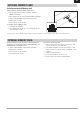
EN PHYSICAL TRANSMITTER ADJUSTMENTS The NX8 has all the physical transmitter adjustments located around the gimbal face of each gimbal. This arrangement allows for quick and easy adjustments with out taking the back cover off or removing any plugs to access adjustment screws.
EN MODE CONVERSION Ratcheted Throttle – Smooth Throttle Adjustment Ratchet: 1. Locate the throttle strap adjustment screws on both gimbals. The ratchet set screw engages a serrated section on the gimbal for a ratcheted throttle, while the tension set screw engages a strap for smooth tension on the gimbal. 2. To engage the throttle ratchet turn the ratchet set screw clockwise until the ratchet engages. 3. To disengage the throttle ratchet turn the screw counter clockwise until the gimbal moves freely.
EN TROUBLESHOOTING GUIDE Problem Aircraft will not bind (during binding) to transmitter Aircraft will not link (after binding) to transmitter Possible Cause Solution Transmitter too near aircraft during binding process Move powered transmitter a few feet from aircraft, disconnect and reconnect flight battery to aircraft Aircraft or transmitter is too close to large metal object Move the aircraft or transmitter away from the large metal object The bind plug is not installed correctly in the bind po
EN 1-YEAR LIMITED WARRANTY What this Warranty Covers Horizon Hobby, LLC, (Horizon) warrants to the original purchaser that the product purchased (the “Product”) will be free from defects in materials and workmanship for a period of 1 year from the date of purchase.
EN WARRANTY AND SERVICE CONTACT INFORMATION Country of Purchase United States of America Horizon Hobby Contact Information Horizon Service Center (Repairs and Repair Requests) servicecenter.horizonhobby.com/ RequestForm/ productsupport@horizonhobby.com Horizon Product Support (Product Technical Assistance) 877-504-0233 Sales EU Address 2904 Research Rd Champaign, Illinois, 61822 USA websales@horizonhobby.com 800-338-4639 Horizon Technischer Service service@horizonhobby.
EN FAA INFORMATION Prior to flying, contact your local or regional modeling organizations for guidance and familiarize yourself with the current local rules and FAA regulations governing model aviation in your location.More information about model aviation can be found at www.modelaircraft.org. The Federal Aviation Administration can be found online at www.faa.gov. AMA NATIONAL MODEL AIRCRAFT SAFETY CODE http://www.modelaircraft.org/files/105.
IT © 2020 Horizon Hobby, LLC DSM, DSM2, DSMX, the DSMX logo, Bind-N-Fly, BNF, the BNF logo, Spektrum AirWare, STi, ModelMatch, AS3X, SmartSafe, and the Horizon Hobby logo are trademarks or registered trademarks of Horizon Hobby, LLC. The Spektrum trademark is used with permission of Bachmann Industries, Inc. US 7,391,320. US 9,930,567. US 10,419,970. Other patents pending. www.spektrumrc.com Updated 09/2020 • 65607.