HORIZON HOBBY, LLC. Specification for Spektrum® X-Bus Telemetry Sensors Enabling Use of Non-Spektrum Sensors Rev E 2016 February 16 Specification for communicating on the X-Bus so that data from non-Spektrum devices can be displayed on the AirWareTM -based transmitters.
Specification for Spektrum X-Bus Telemetry Sensors Specification for Spektrum® X-Bus Telemetry Sensors 1 INTRODUCTION With the advent of third-party display (J-Link), annunciation (vSpeak), and data display systems (Robo-Software), we feel it is in everybody's best interests to open the telemetry system by sharing correct implementation data.
Specification for Spektrum X-Bus Telemetry Sensors Spektrum X-Bus Telemetry Data Application End User License Agreement This End User License Agreement (“Agreement”) is a binding agreement between the reader of this publication (“you”) and Horizon Hobby, LLC (“Horizon”). This Agreement governs your use of the Spektrum X-Bus Telemetry Data as outlined in this publication (“The Telemetry System”). The Telemetry System is licensed, not sold, to you.
Specification for Spektrum X-Bus Telemetry Sensors REQUIREMENTS, ACHIEVE ANY INTENDED RESULTS, BE COMPATIBLE OR WORK WITH ANY OTHER SOFTWARE, APPLICATIONS, SYSTEMS OR SERVICES, OPERATE WITHOUT INTERRUPTION, MEET ANY PERFORMANCE OR RELIABILITY STANDARDS OR BE ERROR FREE OR THAT ANY ERRORS OR DEFECTS CAN OR WILL BE CORRECTED. 4. Limitation of Liability.
Specification for Spektrum X-Bus Telemetry Sensors Furthermore, you agree that Horizon assumes no responsibility for the content you submit or make available through this publication. 7. Severability. If any provision of this Agreement is illegal or unenforceable under applicable law, the remainder of the provision will be amended to achieve as closely as possible the effect of the original term and all other provisions of this Agreement will continue in full force and effect. 8. Governing Law.
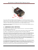
Specification for Spektrum X-Bus Telemetry Sensors SDA SCL Servo Bus +V Common Every device shall be responsible to regulate the supply to a level useful for its operation. The I2C signals must be 3.3V logic, and the pins in open drain mode so as to not interfere with the logic levels. In order to maintain compatibility with other products, it is strongly urged that any sensors include two X-Bus ports to allow them to be daisy-chained in the same manner as Spektrum sensors.
Specification for Spektrum X-Bus Telemetry Sensors 7 ADDRESSING & DEVICE TYPES The Appendix includes the telemetry header file used by all Spektrum AirWare-based transmitters. It defines the device type codes for all Spektrum products and known reserved values. The device type codes are used as I2C bus addresses by default, but the protocol also provides a means for them to differ. Spektrum reserves the right to use addresses not listed as we deem necessary.
Specification for Spektrum X-Bus Telemetry Sensors 9 ELECTRONIC SPEED CONTROL The AirWare-based transmitters may include support for a generic Electronic Speed Control (ESC) device. Spektrum does not sell a device which conforms to this telemetry standard, but is instead providing a common interface which may be supported by ESC manufacturers. The ESC configuration screen provides the same functions available to other devices, that is, whether the status is actively monitored on the display.
Specification for Spektrum X-Bus Telemetry Sensors The “mAh” configuration screen provides the same functions available to other devices, that is, whether the status is actively monitored on the display. Alarms are available for the following conditions: • Battery 1 capacity consumed > user-defined value • Current 1 too high • Temperature 1 too high The units and ranges for each of the fields in the telemetry message are found in the appendix in the definition for the MAH structure.
Specification for Spektrum X-Bus Telemetry Sensors 14 INDIVIDUAL CELL MONITOR The AirWare-based transmitters may include support for a generic multi-tap voltage monitoring device. Spektrum does not sell a device which conforms to this telemetry standard, but is instead providing a common interface which may be supported by third-party manufacturers.
Specification for Spektrum X-Bus Telemetry Sensors custom devices. These devices do not have any alarm capability. The transmitter does not provide any filtering of data for any fields.
Specification for Spektrum X-Bus Telemetry Sensors APPENDIX – HEADER FILE DATA Note that some device types cannot be used by third-party devices, in particular voltage (0x01) and temperature (0x02), as these are reserved for internal use within the transmitter. The text below has been re-formatted for tabs that look good on the page. If you copy/paste them into your code, you will probably want to re-tab them.
Specification for Spektrum X-Bus Telemetry Sensors #define #define #define #define #define #define #define #define #define #define TELE_DEVICE_RSV_6B TELE_DEVICE_RSV_6C TELE_DEVICE_RSV_6D TELE_DEVICE_RSV_6E TELE_DEVICE_RSV_6F TELE_DEVICE_RSV_70 TELE_DEVICE_FRAMEDATA TELE_DEVICE_RPM TELE_DEVICE_QOS TELE_DEVICE_MAX (0x6B) (0x6C) (0x6D) (0x6E) (0x6F) (0x70) (0x7D) (0x7E) (0x7F) (0x7F) // // // // // // // // // // Reserved Reserved Reserved Reserved Reserved Reserved Transmitter frame data RPM sensor RxV +
Specification for Spektrum X-Bus Telemetry Sensors INT16 current_A; INT16 chargeUsed_A; UINT16 temp_A; INT16 current_B; INT16 chargeUsed_B; UINT16 temp_B; UINT16 spare; } STRU_TELE_MAH; // // // // // // // // // Instantaneous current, 0.1A (0-3276.8A) Integrated mAh used, 1mAh (0-32.766Ah) Temperature, 0.1C (0-150.0C, 0x7FFF indicates not populated) Instantaneous current, 0.1A (0-6553.4A) Integrated mAh used, 1mAh (0-65.534Ah) Temperature, 0.1C (0-150.
Specification for Spektrum X-Bus Telemetry Sensors sField2, sField3; UINT16 uField1, uField2, uField3, uField4; } STRU_TELE_USER_16SU; // Unsigned 16-bit data fields ////////////////////////////////////////////////////////////////// // // THIRD-PARTY 16-BIT SIGNED/UNSIGNED AND 32-BIT UNSIGNED // ////////////////////////////////////////////////////////////////// // typedef struct { UINT8 id; // Source device = 0x52 UINT8 sID; // Secondary ID INT16 sField1, // Signed 16-bit data fields sField2; UINT16 uFiel
Specification for Spektrum X-Bus Telemetry Sensors UINT16 volt2; UINT16 capacity1; UINT16 capacity2; UINT16 spare16_1; UINT16 spare16_2; UINT8 spare; UINT8 alarms; } STRU_TELE_POWERBOX; // Volts, 0.
Specification for Spektrum X-Bus Telemetry Sensors } STRU_TELE_VARIO_S; ////////////////////////////////////////////////////////////////// // // ALTIMETER // ////////////////////////////////////////////////////////////////// // typedef struct { UINT8 identifier; UINT8 sID; // Secondary ID INT16 altitude; // .1m increments INT16 maxAltitude; // .
Specification for Spektrum X-Bus Telemetry Sensors JETCAT_ECU_STATE_WAIT_for_RPM = 0x01, // (Stby/Start) JETCAT_ECU_STATE_Ignite = 0x02, JETCAT_ECU_STATE_Accelerate = 0x03, JETCAT_ECU_STATE_Stabilise = 0x04, JETCAT_ECU_STATE_Learn_HI = 0x05, JETCAT_ECU_STATE_Learn_LO = 0x06, JETCAT_ECU_STATE_UNDEFINED = 0x07, JETCAT_ECU_STATE_Slow_Down = 0x08, JETCAT_ECU_STATE_Manual = 0x09, JETCAT_ECU_STATE_AutoOff = 0x10, JETCAT_ECU_STATE_Run = 0x11, // (reg.
Specification for Spektrum X-Bus Telemetry Sensors XICOY_ECU_STATE_Start_On = 0x5F, XICOY_ECU_STATE_Pre_Heat = 0x60, XICOY_ECU_STATE_Battery = 0x61, XICOY_ECU_STATE_Time_Out = 0x62, XICOY_ECU_STATE_Overload = 0x63, XICOY_ECU_STATE_Igniter_Fail = 0x64, XICOY_ECU_STATE_Burner_On = 0x65, XICOY_ECU_STATE_Starting = 0x66, XICOY_ECU_STATE_SwitchOver = 0x67, XICOY_ECU_STATE_Cal_Pump = 0x68, XICOY_ECU_STATE_Pump_Limit = 0x69, XICOY_ECU_STATE_No_Engine = 0x6A, XICOY_ECU_STATE_Pwr_Boost = 0x6B, XICOY_ECU_STATE_Run_Id
Specification for Spektrum X-Bus Telemetry Sensors UINT16 course; UINT8 HDOP; UINT8 GPSflags; } STRU_TELE_GPS_LOC; typedef struct { UINT8 identifier; UINT8 sID; UINT16 speed; UINT32 UTC; UINT8 numSats; UINT8 altitudeHigh; } STRU_TELE_GPS_STAT; // BCD, 3.1 // BCD, format 1.1 // see definitions below // // // // // // Source device = 0x17 Secondary ID BCD, knots, format 3.1 BCD, format HH:MM:SS.S, format 6.1 BCD, 0-99 BCD, meters, format 2.
Specification for Spektrum X-Bus Telemetry Sensors INT16 INT16 INT16 INT16 } STRU_TELE_ATTMAG; attYaw; // // // // // magX; magY; magZ; Yaw is a rotation about the Z Axis of the vehicle using the RHR.
Specification for Spektrum X-Bus Telemetry Sensors typedef union { UINT16 STRU_TELE_QOS STRU_TELE_RPM STRU_TELE_FRAMEDATA STRU_TELE_ALT STRU_TELE_SPEED STRU_TELE_ENERGY_DUAL STRU_TELE_VARIO_S STRU_TELE_G_METER STRU_TELE_JETCAT STRU_TELE_JETCAT2 STRU_TELE_GPS_LOC STRU_TELE_GPS_STAT STRU_TELE_GYRO STRU_TELE_ATTMAG STRU_TELE_POWERBOX STRU_TELE_ESC STRU_TELE_FUEL STRU_TELE_MAH STRU_TELE_DIGITAL_AIR STRU_TELE_STRAIN STRU_TELE_LIPOMON STRU_TELE_USER_16SU STRU_TELE_USER_16SU32U STRU_TELE_USER_16SU32S STRU_TELE_USE
Specification for Spektrum X-Bus Telemetry Sensors REVISION HISTORY Rev P0 P1 P2 P3 P4 P5 Date 2013-03-28 2013-04-04 2013-07-08 2013-07-10 2013-07-16 2013-11-19 Author AK AK AK AK AK AK P6 P7 A B B’ C D E 2014-03-31 2014-05-05 2015-01-16 2015-01-23 2015-11-24 2015-12-28 2015-12-30 2016-02-16 AK AK AK AK TB AK AK AK Description For initial review. Fix address in JetCat_2 struct definition. Add RF data type/struct (Bug MD 1000). Add Gyro and Attitude/Compass info. Add 0x43 as reserved address.