EN AR7110/AR7110R User Guide AR7110/AR7110R Bedienungsanleitung AR7110/AR7110R Guide de l’utilisateur AR7110/AR7110R Guida per l’utente 1
EN NOTICE All instructions, warranties and other collateral documents are subject to change at the sole discretion of Horizon Hobby, Inc. For up-to-date product literature, visit horizonhobby.com and click on the support tab for this product.
EN DSMX ® Spektrum launched the 2.4GHz RC revolution with its DSM2™ technology. Since then, millions of hobbyists the world over have come to embrace 2.4 as the way to fly. Spektrum leads the way yet again with DSMX—the world’s first wideband, frequency-agile 2.4GHz signal protocol. How Does DSMX Work? It’s a crowded 2.4GHz world out there and every 2.4GHz system faces the same challenges.
EN Is DSMX Compatible with DSM2? Yes. DSMX is fully compatible with all DSM2 hardware. In fact, many pilots may find the DSM2 equipment they have now is all they will ever need. Even if a new DSMX transmitter eventually comes along that they really want, all the DSM2 receivers they have now will work with it. It is important to note, however, that while DSMX is compatible with DSM2, the only way to experience the full benefits of DSMX in a busy 2.
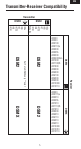
EN Transmitter-Receiver Compatibility Transmitter DSMX DSM2 DX5e DX6i DX7 DX7SE DX8 DX10t DX5e DX6i DX7 DX7SE DX8 DX10t Modules AR600 AR6115/e AR6210 AR6255 AR7010 AR7110/R AR7610 AR8000 AR9010 AR9110 AR9210 AR9310 AR10000 AR12010 AR12110 DSMX 5 Receiver DSM2 DSM2 DSMX DSM2 Set Tx to DSM2 only **note 1 DSM2 AR500 AR600 AR6100 AR6110/e AR6200 AR6255 AR6300 AR6400/ALL AR7000 AR7100/R AR7600 AR8000 AR9000 AR9100 AR9200 AR9300 AR12000 AR12110
EN AR7110/AR7110R User Guide Spektrum AR7110 series receivers offer the ultimate system for high-performance nitro or 500-class and larger electric helicopters. Combining the bullet proof radio link of Spektrum DSM2 technology with a built-in regulator for the Rudder, Aux2, Gear and Throttle channels and an integrated RevLimit limiter (AR7110R only), the AR7110 series receivers make installation of these normally complex devices clean and simple.
EN Note: The AR7110/AR7110R uses a specifically designed switch. Conventionally wired switches are not compatible with the AR7110. Important: The AR7110 and AR7110R require that at least one remote receiver (included) be plugged into port B or R to operate. Applications • All sizes of nitro powered helicopters • 500-class and larger electric helicopters Specifications: AR7110/AR7110R Type: DSM Full Range receiver Channels: 7 Modulation: DSM2, DSMX Dimensions: 1.86 in x 1.58 in x 0.56 in (47.3mm x 40.
EN Battery Requirements IMPORTANT: DO NOT use a 4-cell 4.8-volt battery to power the AR7110/ AR7110R. Because of the built-in regulator the AR7110/AR7110R has a minimum recommended operational battery voltage of 5.5 volts and is designed to use 6-volt 5-cell NiMH, 7.2-volts 6-cell NiMH or 7.4-volt 2-cell LiPo batteries. (Higher voltage should be used only if the servos are compatible.) While the AR7110 will continue to operate down to 3.5 volts, the AR7110/ AR7110R features a built-in 5.
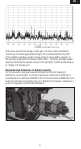
EN In the above example the average current was 1.15 amps, which calculates to 153mAh per 8 minutes (typical flight length). It’s recommended that only 60% of the available capacity be used to ensure plenty of reserve battery capacity. In this example using 2000mAh batteries 2000 x 60% = 1200mAh (available usable capacity) divided by the capacity used per 8 minute flight, 153mAh would allow up to 7 flights of 8 minutes each.
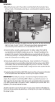
EN Installation •M ount the Receiver unit in the position recommended by the helicopter manufacturer. Foam or thick double-sided tape is recommended to isolate the receiver from vibration. •M ount the switch and insert the switch plug into the port in the main unit marked SWITCH. Note: The AR7110/AR7110R uses a specifically designed switch. Conventionally wired switches are not compatible with the AR7110.
EN Bracket adjusted for 90-size engine Bracket adjusted for 50-size engine • P lug the servo leads and rpm sensor into the appropriate ports in the receiver. • You are now ready to bind the system. Note: In order for the system to operate, one remote receiver must be plugged into receiver port B or R. Connections The throttle and gear channels have two outputs. Output 1 is unregulated and the pack voltage is provided at this port. Throttle and Gear outputs 2 are regulated to 5.
EN 3. P ower the receiver through the EC3 connector. Note all of the receivers (internal and remote) should be flashing indicating they are in bind mode. 4. U sing a second battery, insert the battery plug into any un-used channel in the receiver while pressing and holding the bind button on the side of the telemetry module. This will place the telemetry module in bind mode. 5. M ake sure that the LEDs are flashing on all receivers and on the telemetry module.
EN Failsafe Functions The AR7110/AR7110R PowerSafe features two types of failsafe: SmartSafe™ and Preset Failsafe. SmartSafe Failsafe This type of failsafe is recommended for most types of giant-scale aircraft. Here’s how SmartSafe works: Receiver Power Only When the receiver only is turned on (no transmitter signal is present), all servos except for the throttle are driven to their preset failsafe positions, normally all control surfaces at neutral and the landing gear down.
EN After Connection When the transmitter and receiver are turned on and after the receiver connects to the transmitter and normal control of all channels occurs, if loss of signal occurs Preset Failsafe drives all servos to their preset failsafe positions. For sailplanes it’s recommended that the spoilers/flaps deploy to dethermalize the aircraft, preventing a flyaway. Some modelers prefer to use this failsafe system to program a slight turn and low throttle to prevent their aircraft from flying away.
EN Advanced Range Testing Using a Flight Log The Standard Range Testing procedure is recommended for most sport aircraft. For sophisticated aircraft that contain significant amounts of conductive materials (e.g. turbine powered jets, some types of scale aircraft, aircraft with carbon fuselages, etc.), the following advanced range check will confirm that all remote receivers are operating optimally and that the installation (position of the receivers) is optimized for the specific aircraft.
EN Flight Log The Spektrum Flight Log (SPM9540) is compatible with the AR7110/AR7110R PowerSafe. The Flight Log displays overall RF link performance as well as the individual internal and external receiver link data. Additionally it displays receiver voltage. Using the Flight Log After a flight and before turning off the receiver or transmitter, plug the Flight Log into the Data port on the PowerSafe. The screen will automatically display voltage e.g. 6v2= 6.2 volts. When the voltage reaches 4.
EN RevLimit Instructions (AR7110R only) The Spektrum AR7110R features an integrated RevLimit limiter. The RevLimit functions as a digital rpm limiter preventing the main rotor from over-speeding. When the rotor speed is at or below the programmed rpm, throttle position is controlled via the radio (i.e. throttle curves). The RevLimit only engages when the rotor rpm exceeds the programmed rpm reducing the throttle position preventing over-speed.
EN Modes of Operation The RevLimit target rpm is adjusted thru the Gear channel (channel 5) output. DX7 In system setup mode program AUX2 to GYRO and GEAR to AUX2, the RevLimit will be controlled and adjusted via the AUX2 switch, and all the target rpm’s will be adjusted using the GEAR channel travel adjust. The Gyro Gain channel will plug into the AUX2 channel and the gyro screen will be used to adjust the gyro gain (see the DX7 manual for more detail on gyro gain settings).
EN JR X9303 2.4GHz In System mode under device, activate the limiter program by selecting GOV under the Gear channel. The RevLimit will then be controlled and adjusted via the Limiter screen located in function mode. A target rpm is available for each flight mode. 0% turns off the limiter, while the larger the value the higher the target rpm. The Gyro Gain channel will plug into the Gear channel and the gyro screen will be used to adjust the gyro gain.
EN Calibration Important: When calibrating the system, the limiter percentages must be adjusted to 100% normal and -100% in ST1. During calibration the RevLimit stores the output limits of the Gear channel. It’s necessary to adjust the Gear channel output to 100% in both directions during calibration. 1. Adjust the throttle operation so that the servo travel is near 100% in both directions at full throttle and at full idle. This may require lengthening or shortening the servo horn. 2.
EN Setting a Target RPM The Gear channel’s output sets the target rpm. See the diagram below. Note that the limiter is turned off from 0% to 5% and the target rpm is increased as the travel adjust/limiter setting is increased. Also note that the rpm increases above and below 5%. Using the servo monitor is a helpful way of verifying adjustment. Adjust the gear channel’s travel adjust (DX7) or the limiter program to select the desired target rpm’s. Fig: Auxiliary Channel ATV to Target Speed.
EN The RevLimit will pass control back to the throttle channel (controlled by the throttle curves) if any of the following occurs: 1. The throttle stick (output) is below 25%. 2. T he Gear channel output is less than 5% (travel adjust or limiter setting). 3. The rpm sensor fails. QuickConnect™ with Brownout Detection The remote receivers now included with the AR7110/AR7110R feature QuickConnect with Brownout Detection (Brownout Detection not available with DSMX).
EN 2.
EN Problem The system will not connect Possible Cause Solution Your transmitter and receiver are too close together.
EN 1-Year Limited Warranty What this Warranty Covers Horizon Hobby, Inc., (Horizon) warrants to the original purchaser that the product purchased (the “Product”) will be free from defects in materials and workmanship for a period of 1 years from the date of purchase.
EN WARRANTY SERVICES Questions, Assistance, and Services Your local hobby store and/or place of purchase cannot provide warranty support or service. Once assembly, setup or use of the Product has been started, you must contact your local distributor or Horizon directly. This will enable Horizon to better answer your questions and service you in the event that you may need any assistance. For questions or assistance, please direct your email to productsupport@ horizonhobby.com, or call 877.504.
EN Warranty and Service Contact Information Country of Purchase Horizon Service Center United States of America United Kingdom Germany France China Phone Number/Email Address Horizon Hobby Address 4105 Fieldstone Rd Champaign, Illinois 61822 USA (Electronics and engines) Horizon 4105 Fieldstone Rd Product Champaign, Illinois Support (All 61822 USA other products) Units 1-4 Ployters Rd Staple Tye Horizon Hobby Harlow, Essex Limited CM18 7NS United Kingdom Christian-JungeHorizon Straße 1 Technischer
EN Country of Purchase France China Phone Number/Email Address Horizon Hobby Address 14 Rue Gustave Eiffel Horizon Hobby Zone d’Activité du SAS Réveil Matin 91230 Montgeron Room 506, No. 97 Horizon Hobby Changshou Rd. – China Shanghai, China 200060 +33 (0) 1 60 47 44 70 infofrance@horizonhobby. com +86 (021) 5180 9868 info@horizonhobby. com.cn Compliance Information for the European Union Declaration of Conformity (in accordance with ISO/IEC 17050-1) No.
DE HINWEIS Alle Anweisungen, Garantien und anderen zugehörigen Dokumente können im eigenen Ermessen von Horizon Hobby, Inc. jederzeit geändert werden. Die aktuelle Produktliteratur finden Sie auf horizonhobby.com unter der Registerkarte „Support“ für das betreffende Produkt.
DE DSMX Spektrum hat die RC Technologie mit dem DSM2 System revolutioniert und damit Millionen von RC Hobbyfreunden zu zufriedenen Nutzern des 2,4 Ghz Systems gemacht. Spektrum setzt jetzt mit dem DSMX System wieder Meilensteine. DSMX ist weltweit das erste Breitband Frequenz agile 2,4 Ghz Signalprotokoll. Wie arbeitet DSMX ? Die Nutzer des 2,4 GHz Frequenzbereich werden immer mehr und durch diese Menge steht jedes System vor der Herrausforderung auch in Zukunft eine sichere Übertragung zu gewährleisten.
DE Wie gut ist DSMX ? In multiplen Tests wurden für einen langen Zeitraum 100 DSMX Systeme gleichzeitig betrieben. Während der Tests wurde jedes DSMX System im Flug und am Boden überwacht. In jedem Test wurde kein Verlust der RF Verbindung, Verringerung der Latenzzeit oder ein Qualitätsverlust der Verbindung aufgezeichnet. Ist DSMX kompatibel mit DSM ? Ja, DSMX ist voll kompabitel zu DSM2. Viele Piloten haben mit ihrer DSM2 Ausrüstung das gefunden was sie für Ihr Hobby brauchen.
DE Sender – Empfänger Kompatibilität Sender DSMX DSM2 DX5e DX6i DX7 DX7SE DX8 DX10t DX5e DX6i DX7 DX7SE DX8 DX10t Modules AR600 AR6115/e AR6210 AR6255 AR7010 AR7110/R AR7610 AR8000 AR9010 AR9110 AR9210 AR9310 AR10000 AR12010 AR12110 DSMX 32 Empfänger DSM2 DSM2 DSMX DSM2 Stellen Sender auf DSM2 ausschließlich ** Hinweis 1 DSM2 AR500 AR600 AR6100 AR6110/e AR6200 AR6255 AR6300 AR6400/ALL AR7000 AR7110/R AR7600 AR8000 AR9000 AR9100 AR9200 AR9300 AR12000 AR12110
DE AR7110/AR7110R Bedienungsanleitung Die AR7110 Serie von Spektrum bietet das ultimative Empfangssystem für Hochleistungshelikopter der 500 Klasse oder größere Elektrohelikopter.
DE Hinweis: Der AR7110/AR7110R ist mit einem speziellen Ein/Aus Schalter ausgerüstet und nicht kompatibel zu normalen Schaltern. WICHTIG: Der AR7110/AR7110R benötigen zum Betrieb mindesten einen externen Empfänger ( im Lieferumfang enthalten ) der in den B oder R Anschluß gesteckt werden muß.
DE Anforderungen an die Empfängerstromversorgung WICHTIG: Verwenden Sie keine 4 Zellen 4,8 Volt Akku zur Empfängerstromversorgung. Aufgrund des eingebauten Spannungsreglers des AR7110/AR7110R ist die mindest Arbeitsspannung auf 5,5 Volt geregelt und für 6 Volt 5 Zellen NiMH Akkus, 7,2 Volt 6 Zellen NiMH Akkus oder 7,4 Volt 2S LiPo Akkus ausgelegt.
DE In dem obenstehenden Beispiel beträgt der durchschnittliche Stromverbauch 1,15 Ampere, der sich zu 153mAh per 8 Minuten Flug summiert. Wir empfehlen nur 60% der zur Verfügung stehenden Akku kapazität zu verwenden, um genügend Sicherheitsreserven zu haben. In diesem Beispiel wird ein 2000mAh Akku verwendet. 2000 x 60% (zur Verfügung stehende Kapazität) geteilt durch den Verbrauch per 8 Minuten Flug 153mAh würde 7 Flüge mit je 8 Minuten ermöglichen.
DE Einbau • B auen Sie den Empfänger in der Position ein, die von dem Hersteller des Helikopter dafür vorgegeben wird. Nutzen Sie dickes geschäumtes doppelseitiges Klebeband um den Empfänger vor Vibrationen zu schützen. •M ontieren Sie den Schalter an gewünschter Stelle und schließen Sie ihn am Empfänger an dem Anschluß SWITCH an. Die AR7110/AR7110R benutzen einen speziellen Ein/Aus Schalter der nicht kompatibel zu normalen Schaltern ist.
DE Klemme eingestellt für 90er Helikopter Klemme eingestellt für 50er Helikopter • S chließen Sie die Servostecker und den Drehzahlsensor in die dafür vorgesehenden Anschlüsse an. • Das System ist nun fertig zum Binden. Hinweis: Für ein betriebsbereites System muß mindestens ein externer Empfänger in den Anschluß B oder R gesteckt werden.
DE 2. Stecken Sie das Datenkabel vom Telemetriemodul in einen beliebigen ungenutzten Kanal des Empfängers. (Sollten alle Kanäle belegt sein entfernen Sie ein Servokabel und stecken dort das Datenkabel ein) 3. Schalten Sie den Empfänger mit Anschluß des EC3 Steckverbinders ein. Bitte beachten Sie, dass alle Empfänger LEDs (intern und Satellit) nun blinken sollten und damit den Bindevorgang anzeigen. 4.
DE Failsafe Funktionen Der AR7110/AR7110R bietet zwei Failsafe Funktionen: SmartSafe und Preset Failsafe SmartSafe Failsafe Diese Failsafe Einstellung ist für große Scale Modelle zu empfehlen. So arbeitet SmartSafe: Empfänger ist eingeschaltet (ohne Sender) Wenn der Empfänger eingeschaltet ist, fahren alle Servos mit Ausnahme des Gaskanals in Ihre programmierten Failsafe Positionen. (normalerweise alle Ruder auf neutral und Fahwerk ausgefahren).
DE zu verhindern. Einige Piloten programmieren das Einsteuern in eine leichte Kurve um das Modell am Wegfliegen zu hindern. Ist das Signal wieder da, wird sich das System in weniger als 4ms wieder binden.
DE Reichweitentest mit dem Flight Log Der Standard Reichweitentest ist grundsätzlich für jedes Flugmodell empfohlen. Für Flugzeuge, die einen Anteil an abschirmenden Materialen haben (z.B Turbinen Jets, einige Typen von Scale Flugzeugen sowie Modelle mit Carbon/ Kohlefaserbauteilen etc.) ist der Reichweitentest mit dem Flight Log angebracht. Mit diesem Test kann die Empfangsleistung jedes einzelnen Empfängers überprüft werden. 1.
DE Flight Log Spektrums Flight Log (SPM9540) ist kompatibel mit demAR7110/AR7110R PowerSafe. Das Flight Log zeichnet die Gesamtempfangsleistung auf, sowie die Empfangsleistung jeder einzelnen Antenne. Zusätzlich zeigt das Gerät auch die Empfängerakkuspannung an. So nutzen Sie das Flight Log: Nach dem Flug bevor Sie den Empfänger ausschalten stecken Sie das Flight Log in den Datenport des PowerSafe Empfängers. Das Display zeigt ihnen dann automatisch die Spannung an 6v2 = 6,2 Volt..
DE Der Drehzahlbegrenzer (nur AR7110R) Der Spektrum AR7110R ist mit einem integrierten Drehzahlbegrenzer (Limiter) ausgestattet. Dieser Begrenzer schützt den Hauptrotorantrieb vor dem Überdrehen. Ist die Rotorgeschwindigkeit unter dem eingestellten Limit hat der Begrenzer keine Funktion und die Gaskurve des Senders regelt den Hauptrotor. Der Begrenzer greift nur ein wenn die Drehzahl den eingestellten Wert übertrifft und schützt somit das Rotorsystem vor dem Überdrehen.
DE Funktionseinstellung Die Zieldrehzahl des Drehzahlbegrenzers wird über den Fahrwerkskanal (Gear) Kanal 5 eingestellt. DX7 Wählen Sie im Set Up Mode unter der Auswahl INPUT Select AUX2 zu GYRO und GEAR zu AUX2. Der Drehzahlbegrenzer wird über den AUX2 Schalter kontrolliert und geschaltet. Die Zieldrehzahl des Begrenzers wird über den Travel Adjust des (Fahrwerk) GEAR Kanals eingestellt. (Sehen Sie bitte hierzu auch in der Bedienungsanleitung der DX7 auf Seite 73 und 74 nach).
DE JR X9303 2.4GHz Im System Mode unter Auswahl aktivieren Sie das Begrenzerprogramm in dem Sie GOV (Governour) bei dem Fahrwerkskanal auswählen. Der Drehzahlbegrenzer wird dann über das Display im Funktions Mode eingestellt. Eine Zieldrehzahl ist für jeden Flugmode verfügbar. 0% schaltet den Limiter ab, je höher der gewähle Wert ist, desto höher ist die Begrenzerdrehzahl. Der Kreisel Kanal wird über den GEAR Kanal eingestellt .
DE Kalibrierung WICHTIG: Wenn das System kalibriert wird ist es wichtig dass die Begrenzereinstellung auf 100% normal und - 100% in Schritt 1 gestellt wird. Während der Kalibrierung speichert der Limiter den Weg des Fahrwerksservo (Gear). Es ist daher notwendig, dass der Servoweg auf beiden Seiten 100% beträgt. 1. Stellen Sie den Weg des Gasservos so ein, dass der Weg zu beiden Seiten 100% beträgt. Dieses kann bedeuten, dass Sie am Servohorn die Anlenkung umstecken müssen. 2.
DE Einstellen der Begrenzerdrehzahl Die Einstellung der Ausgabe des Fahrwerkskanal stellt die Begrenzerdrehzahl ein. Bitte beachten Sie dazu das unten stehende Diagramm. Bitte beachten Sie, dass der Begrenzer bei einer Einstellung von 0 - 5% deaktiviert ist. Die Drehzahl erhöht sich analog zu dem gewählten Travel Adjust Wert. Der Servomonitor ist hier hilfreich zur Einstellung. Zusatzkanal ATV zu Speed Target.
DE Der Begrenzer gibt die Kontrolle zurück auf dem Gaskanal (kontrolliert von der Gaskurve) wenn folgendes passiert. 1. Der Gasstick ist auf unter 25% 2. Der Fahrwerks (Gear) Signal ist kleiner als 5% ( Travel Adjust oder Begrenzereinstellung) 3. Ausfall der Drehzahlsensors QuickConnect™ mit Unterspannungsanzeige (Brownout) Ihr AR7110 verfügt über die QuickConnect Funktion mit der Unterspannungsanzeige.
DE 2.4GHz Hilfestellung zur Problemlösung Problem Flugzeug nimmt kein Gas an, allen anderen Kontrollen funktionieren. LED auf dem Empfänger blinkt, Flugzeug ist nicht zu kontrollieren. Mögliche Ursache Lösung Gas und oder GasTrimmung sind nicht in der untersten Position vor dem Einschalten.
DE Problem Das System will sich nicht verbinden. Mögliche Ursache Lösung Sender und Empfänger stehen zu nah zusammen. Die Entfernung sollte 2,64 - 3,96 Meter betragen. Entfernen Sie den Sender 2,64 - 3,96 Meter vom Empfänger. Sie sind von metallischen Objekten umgeben. Suchen Sie sich eine Umgebung mit weniger metallischen Objekten. Das gewählte Modell ist nicht das gebundene Modell. Überprüfen Sie das gewählte Modell und stellen Sie sicher, dass es gebunden ist.
DE Garantie und Service Informationen Garantiezeitraum Exklusive Garantie Horizon Hobby Inc (Horizon) garantiert, dass das gekaufte Produkt (Produkt) frei von Material- und Montagefehlern ist. Der Garantiezeitraum entspricht den gesetzlichen Bestimmung des Landes, in dem das Produkt erworben wurde. In Deutschland beträgt der Garantiezeitraum 6 Monate und der Gewährleistungszeitraum 18 Monate nach dem Garantiezeitraum.
DE Wenn Sie als Käufer nicht bereit sind, diese Bestimmungen im Zusammenhang mit der Benutzung des Produktes zu akzeptieren, werden Sie gebeten, dass Produkt in unbenutztem Zustand in der Originalverpackung vollständig bei dem Verkäufer zurückzugeben. Sicherheitshinweise Dieses ist ein hochwertiges Hobby Produkt und kein Spielzeug. Es muss mit Vorsicht und Umsicht eingesetzt werden und erfordert einige mechanische wie auch mentale Fähigkeiten.
Achtung: Kostenpflichtige Reparaturen nehmen wir nur für Elektronik und Motoren vor. Mechanische Reparaturen, besonders bei Hubschraubern und RC-Cars sind extrem aufwendig und müssen deshalb vom Käufer selbst vorgenommen werden. Sicherheit und Warnungen Als Anwender des Produktes sind Sie verantwortlich für den sicheren Betrieb aus dem eine Gefährdung für Leib und Leben sowie Sachgüter nicht hervorgehen soll.
DE EN Konformitätserklärung gemäß Gesetz über Funkanlagen und Telekominikationseinrichtungen (FTEG): Declaration of Conformity accordance with the Radio and Telecommunications Terminal Equipment Act (FETG) and directive 1999/5/EG (R&TTE) Horizon Hobby GmbH Christian-Junge-Straße 1 25337 Elmshorn erklärt das Produkt: AR7110/AR7110R Rx SPMAR7110/SPMAR7110R declares the product: AR7110/AR7110R Rx SPMAR7110/SPMAR7110R Geräteklasse: 1 equipment class: 1 den grundleegenden Andforderungen des §3 und den übrige
© 2012 Horizon Hobby, Inc. The Spektrum trademark is used with permission of Bachmann Industries, Inc. All other marks are trademarks or registered trademarks of Horizon Hobby, Inc. US 7,391,320. Other patents pending. Created 1/12 30960.