TABLE OF CONTENTS Introduction 1. Important Safety Instructions................................................................................ 1 2. Assembling Your Treadmill.................................................................................... 4 Installation Requirements..................................................................................... 4 List of Parts........................................................................................................... 4 3.
Your SportsArt treadmill was designed and built for optimum safety. However, certain precautions apply whenever you use your treadmill. Please read the entire manual before assembly and operation. Also, please note and save the following safety instructions: IMPORTANT SAFETY INSTRUCTIONS DANGER - To reduce the risk of electric shock: Improper connection of the equipment-grounding connector can result in a risk of electric shock.
11) The weight limit for this treadmill is 300 Ib. (135 kg) 12) Do not operate where aerosol (spray) products are being used or where oxygen is being administered. 13) To disconnect, turn all controls to the off position, then remove plug from outlet. 14) Assemble and operate the treadmill on a solid, level surface. Keep the area behind the treadmill clear. 15) Never allow children on or near the treadmill. The running belt will not stop immediately if any object becomes caught in the belt or rollers.
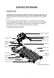
SPORTSART TR32 TREADMILL INTRODUCTION Congratulations on purchasing one of the finest piece of exercise equipment on the market today, the SportsArt TR32 treadmill. The TR32 is designed with the end user in mind and constructed of high quality materials and designed for years of troublefree use. Before using your SportsArt TR32 treadmill, we recommend that you familiarize yourself with this Owner's Manual.
ASSEMBLING YOUR TREADMILL Installation Requirements Thank you for purchasing a SportsArt Fitness product. For proper installation please read and follow the instructions. If the treadmill is not assembled properly, you could void the SportsArt Fitness Limited Warranty. If there are any parts or tools that are missing please contact your dealer immediately.
16. 3 pcs M5*L10 philips screws (for accessory tray) 17. 4 pcs M4*L12 philips screws (for fan) (option) 18. 2 pcs transition tubing (for long rails) (option) 19. One left long rail (option) 20. One right long rail (option) 21. 6 pcs M6*L10 screws (hole in M4) (for long handle rails) (option) 22. 6pcs washer D20*d7*t2.0 (for long rails) (option) 23. 4 pcs M8*L18 screws(hole in M6) (for long rails) (option) 24.
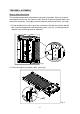
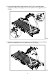
TREADMILL ASSEMBLY Step by Step Instructions The important spare parts are placed into the grid of styrofoam. When you remove the treadmill from its box, first check to make sure all of parts are present before you discard the styrofoam. Thoroughly read the assembly instructions before you begin. 1. Tip the treadmill on its side. Inspect the underside of the belt and confirm that the belt is centered between the belt alignment guides. (see Fig.
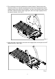
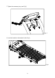
3. The necessary screws are attached onto support bracket. Please remove the fasteners before you assemble upright posts. Insert the left upright post into the support bracket on the left side of treadmill. The hole A should face inside. Place the ribbon cable through the right upright post, then insert right upright post into the support bracket. (see Fig.3) Fig.3 4. Using Hex Allen wrench (M6), secure the two upright posts. At this point, do NOT tighten securely. (see Fig.4) Fig.
5. Connect the upper ribbon cable connector (see Fig.5A). Insert the display electronics package into upright posts. Insert cap onto each upright post. (see Fig.5B) Fig.5 6. Attach the upper fasteners of the upright post, do NOT tighten securely. Tighten fully the lower fasteners, then the upper fasteners. (see Fig.6) Fig.
7. Tighten the accessory tray. (see Fig.7) Fig.7 8. Insert the handle to the treadmill. (See Fig.8) Fig.
9. Fan assembly. This is an optional part. (1) Loosen and take off the shelter. (see Fig.9) Fig.9 (2) Put th fan bracket to accessory tray and tighten. (see Fig.10) Fig.
(3) Pass the wiring from the back of electronic display through the hole on the top of fan cover as shown in Fig.11A. Attach the accessory tray. (see Fig.11) Fig.11 (4) Place the wiring from the display in the clip on the fan assembly as shown in Fig.12A. Follow the wire routing in Fig.12A, and make connection. (See Fig.12B) Fig.
(5) Assemble the screws on the bottom of the fan cover. (see Fig.13) Fig.13 10. Long side handrail assembly: (1) Remove endcap fastener and endcap. (see Fig.14) Fig.
(2) Insert short transition tubing into left and right short handrails, align hole for fastener. Place handrail transition ring and insert fasteners on underside of handrail. (see Fig.15) Fig.15 (3) Assemble the left and right long rails. Tighten the upper then lower fasteners. (see Fig.16) Fig.
11. Assemble the power cord onto treadmill. (see Fig.17) Fig.
TR32 ELECTRONIC DISPLAY: A. Electronics Display Features: Personal CardioAdvisor Information Window ActivZone PERSONAL CardioAd viso r Cardio Training Weight Loss 65% HR TARGET 80% HR TARGET HEART RATE SCAN CALORIES SPEED TIME DISTANCE CAL/HR METS PACE INCLINE ActivZone INTERVAL RANDOM HILL MANUAL To START START 1. Press START 2. Select USER Press Enter 3.
B. Display Features: 1. Personal Cardio Advisor Personal CardioAdvisor is a heart rate training tool that requires your age input to calculate you high and low optimin HR training zone. The center display shows current HR when wearing a chest or contact HR. 2. Information window CALORIES - Total calories burned SPEED - 0.1 to 12 mph in 0.1 increments TIME - 00:00 to 99:59 DISTANCE - 0.
C. Display Controls: 1. START: Press the START button to begin programming. 2. QUICKSTART: Quickstart will bypass User, Age, Weight inputs, and Program seletion. Time will count up. 3. ENTER: Input of information. 4. INTERVAL: Select specific work and rest periods as well control time, incline and speed per period. 5. RANDOM: Infinite number of courses. Continue to press the random button to select a desired course profile. 6. HILL: Press the Hill button repetitively to select from 3 Hill profiles. 7.
10. GLUTE: Program specifically designed for focusing on the gluteus portion of the body. 30 and 45 minute programs run you through a specific incline based program. 11. CARDIO: This program focuses on the lower end of the cardiovascular HR range, optimizing the HR for weight loss. 12. WT LOSS: This program focuses on the lower end of the cardiovascular HR range, optimizing the HR for weight loss. 13. NUMERIC KEYPAD: The keypad can be used to input information during the programming stage. 14.
18. FAN: The fan is an optional part with a 3 speed that will allow the user to select the proper amount of air flow. Safety Key: The safety key feature is required to be in place for the treadmill to operate. This safety device is intented to provide the user a safe mechanism to stop the treadmill should a user stumble and fall. The electonics will prompt with the message - SAFETY KEY, to remind the user to replace the safety key in its proper place.
HOW TO USE YOUR TR32 TREADMILL: Your SportsArt Fitness treadmill has many outstanding and beneficial electronic features that can simplify the programming interface. By thoroughly understanding the electronics you can significantly improve your workout experience. 1. QUICK START and Touch-N-Go QuickStart Programs: A. QUICK START: If you select QUICKSTART the electronics will default to 150Ib user and 35 years old.
2. Press INCLINE ▲ and INCLINE ▼ or press one of digital keys 1~4 to select USER, press ENTER. B. Set your personal ID: This feature allows you to personalize the User ID number. You can enter up to 11 characters. 1. When the desired User ID is displayed, press and hold the CHANGE button for 3 seconds to enter the user personalization process. A scrolling message will display "PRESS INCLINE UP/DN TO INPUT NAME, PRESS ENTER". 2. Press INCLINE ▲ / ▼ to select the letter or number you desire and press ENTER.
5. START WORKOUT: Upon selecting the program, press SPEED UP to begin. During your workout you can change programs without changing the desired time or distance. Shift on the Fly programming allows you to change programs and your time or distance continues per your original settings. 6. COOL DOWN Program: Upon completing the program, the electronics will display accumulative data for your workout. Following, the treadmill will automatically go to a COOL DOWN program. Speed will gently lower to 2.
E. INTERVAL: This program (depending on which model) offers multiple programs. The default setting for the program 1:1 is 1 minute of Rest with 2% incline and 1 minute of Work with 4% incline. These values can be changed at any time during your workout. Once you go into the INTERVAL program, the electronic display will firstly prompt you to enter total workout time. (1) Enter REST time. Please follow up the display information to input TIME, INCLINE and SPEED one by one.
H. PERSONAL TRAINER: This modivational program allows a user the ability to select a workout period and monitor your progress during that time. You can select a 1 month, 2 month, 3 month training period while always monitoring your progress and accumulative data specific to your desired training period. Upon selecting Personal Trainer program, you can choose from the following options. 1. If this is the first time using the program, the electronics will prompt you through the programming process. 2.
GUIDELINES FOR EXERCISE How hard should I exercise? HE Studies show that to achieve the benefits of aerobic exercise, it is necessary to work within your training zone. Your training zone depends on your age and level of fitness. The above chart indicates the recommended Heart Rate training zones (darkened area of the chart). These figuress are calculated by taking 220 minus your age, and calculating 80% for your maximum and 65% for the minimum heart rate for aerobic exercise.
ADJUST THE RUNNING BELT The belt is properly aligned at the factory. However, during shipping and handling or by use on an uneven surface, the belt may move off center. Therefore, it is important that you check the belt's alignment before using the treadmill. The correct alignment of the running belt is critical for the smooth operation of the treadmill. CAUTION: DO NOT ALLOW ANY ONE TO WALK ON RUNNING BELT DURING THIS PROCEDURE. Your treadmill comes with a belt alignment gauge located on the deck.
BELT ADJUSTMENT PROCEDURE 1. Turn on the power switch located on the front of treadmill. Insert the SAFETY KEY on the its position. 2. Press the SPEED ▲ button to increase the speed to 2.0mph / 3.2kph. 3. While the unit is running at 2.0mph/3.2kph, determine where the belt is in relation to the belt alignment gauge. 4. If the belt not be in the green operating range, follow the steps below to return the belt to the proper operating range. 5.
Periodically monitor the position of the belt to ensure peak performance: When you are using the treadmill, if you feel a pause in the belt with each foot plant, the belt may be too loose. Stop the machine to check the belt tension, pull the running belt up in the middle (see Fig.19-1 & 19-2). There should be about 30 m/m (1 1/8") or 3kgs of "give" in the belt (see Fig.19-3). If there is too much, adjust both rear roller bolts clockwise 1/4 turn at a time (see Fig.19-1).
Cushion Adjustment The adjustable cushion feature allows you to change the cushion as your desire. The firm side will set to the least amount of deck movement providing a firm walking or running surface. The soft side will provide a soft walking or running surface. (Fig.20) firm soft Fig.
FLOOR LEVEL ADJUSTMENT If the treadmill rocks or is otherwise unsteady on the floor, turn the leveler as shown to raise or lower the unit. (see Fig.21) Fig.21 TROUBLE SHOOTING Caution: Shut off unit and disconnect power cord before making any repairs or modifications. Error messages 1. Error Message: A. ERR1: Speed sensor circuit error. Contact your local dealer or service provider. B. ERR3: Actual speed is greater than the setting speed. Re-start the unit. C. ERR7: Incline motor calibration issue.
2. Prompted Explanation: FOR ACCURATE HR, HOLD SENSORS FIRMLY WHILE WALKING: Indicates that your heart rate signal is not being detected clearly because your hands are moving on the heat rate handlebars. Incline Fuse Failure The incline fuse is located on the drive board. If this fuse fails, replace it with a good one of the same type. If the incline still does not operate, contact your local dealer or service provider.
Fig.22-1 Fig.22-2 Fig.22 Fig.22-3 If the treadmill does not work after changing the fuse, please contact your dealer for more information. For safety reasons, you may wish to make a treadmill inoperable. To do so, simply remove the fuse.
Wiring Schematic: TR32 Your Authorized Distributor 33