
Use and Care Manual

IN009 Rev N 0120 53 Saber Way, Ward Hill, MA 01835 | spruce.com
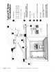
7.0 INSTALLATION
Step 1: Install Mounting Bracket as shown (Fig. 4). Insert Grommets into
slots in Mounting Bracket. Orient the Electrical Box relative to Mounting
Bracket as required. Attach the fan to the Mounting Bracket with 3 #10 self-
tapping screws, provided. Avoid over tightening screws.
Step 2: Select location for fan mounting. A location 2/3 along the ducting, a
minimum of 10 feet away from the inlet vent to the fan or the Y/T of a multi-
intake system- will provide the quietest operation. Fan should be mounted
vertically to prevent moisture from accumulating in the fan housing. Attach
bracket to mounting structure with the 1 1/4” screws provided (Fig. 5).
Step 3: Connect ductwork between fan inlet and area to be vented through
inlet grille (Fig. 6). Flexible, nonmetallic ducting is recommended for
quietest operation and easiest installation. Insulated exible ducting is highly
recommended for bathroom ventilation in all cold climate installations.
Metal worm drive clamps, spring clamps, and adjustable plastic ratchets are
recommended for connection of ducting. Silicon caulk or duct tape may be
used for additional sealing. Duct tape should be used to retain insulation.
Step 4: Connect inlet grille(s) (Fig. 7). An optional backdraft damper may
be installed in the inlet grille to prevent cold air from backing into the inlet,
prevent conditioned air from escaping and also prevent condensation from
forming inside the ductwork. Backdraft dampers are highly recommended at
each intake grille for bathroom ventilation in all cold climate installations.
Step 5: Connect outlet of fan to outside vent (Fig. 8). The outside vent may
go through the roof, sidewall or soft as desired. Flexible, nonmetallic ducting
is recommended for quietest operation and easiest installation. Insulated
exible ducting is highly recommended for bathroom ventilation in all cold
climate installations.
Step 6: Make electrical connection to fan (Fig. 9). Ensure any metal ling
used in the installation is properly grounded. A plastic cable connector such
as a T&B #3300 may be used to avoid any ling grounding problem. Observe
the proper wiring connections (See Section 5.0). Note that the fan is not
intended for connection to rigid metal conduit.
Fig. 4
Fig. 5
Fig. 6
Fig. 7
Fig. 8
Fig. 9
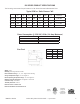
RV Series Wire AC Connection
Black AC Line
White AC Common
Green or Grn/Ye Ground