
Use and Care Manual


9013DB0701 Preventive Maintenance and Troubleshooting Guidelines for Class 9013F and 9013G Pressure Switches
12/2007 Providing Routine Maintenance
© 2007 Schneider Electric All Rights Reserved
3
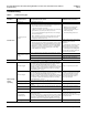
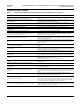
b. Use the table below as a guideline for setting range nut R.
c. Complete Steps 7 and 8 of “Providing Routine Maintenance” on
page 2.
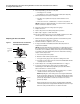
6. To increase or decrease the cut-out setting (while maintaining the same
cut-in pressure) adjust the pressure switch with a 3/8 inch nut driver or
socket as follows:
a. Complete Steps 1–6 of “Providing Routine Maintenance” on page 1.
b. Turn differential nut D clockwise for higher cut-out pressure, or
counter clockwise for lower cut-out pressure. See Figure 1 on
page 2.
NOTE: Adjusting the differential changes the cut-out setting. The
cut-in does not change.
c. Complete Steps 7–9 of “Providing Routine Maintenance” on page 2.
7. Monitor the system to ensure that the pressure setting is as desired.
a. Open a faucet and drain water from the system until the pump turns
on.
b. Turn off the faucet.
c. Monitor the system pressure to identify the point where the pump
turns off.
d. Repeat Steps 5–7 as required.
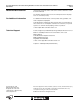
Renewal Parts
Original Setting New Setting
Turn Range Nut R
Clockwise
20-40 30-50 3-1/2 Turns
20-40 40-60 8 to 8-1/2 Turns
30-50 40-60 3-1/2 Turns
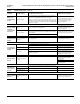
Table 1: Renewal Parts
Description Part Number
9013F 9013G
Contact kit with contact block, contacts, and
diaphragm
9998PC241 9998PC205
Replacement cover
1
1
Include the complete part number of the pressure switch to be used with, including all forms.
65076 605 50 665133 559 50