
Instruction Sheet


© 2006 Schneider Electric USA All Rights Reserved
40269-469-02 QO
®
Circuit Breaker Load Centers
03/2006 Instruction Bulletin
3
INSTALLATION FOR QOT CIRCUIT BREAKERS
NOTE: Square D
®
Class CTL load centers are designed to restrict the
installation of more overcurrent devices than that number for which each was
designed, rated and approved. To accomplish this, the mounting means for
QOT
®
circuit breakers is different from QO
®
and Q1
®
circuit breakers.
Installation
NOTE: Type QOT tandem circuit breakers may be installed only in load
centers where the mounting rail has a slot at the center line of the desired pole
place.
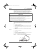
1. Turn OFF (O) circuit breaker.
2. Hold QOT circuit breaker at a 30° angle and insert mounting cam (A) in
mounting rail (B) as far as possible.
3. Rotate circuit breaker until plug-on jaws (C) plug securely onto bus bar
connector (D).
NOTE: Bottom of circuit breaker case should remain against mounting rail.
4. Install wires.
Removal
1. Turn OFF (O) circuit breaker.
2. Remove wires.
3. Disconnect circuit breaker by rotating the plug-on jaws (C) away from bus
bar connector (D) until the jaws disengage.
4. Remove circuit breaker from the mounting rail (B).
Figure 3: Tandem Circuit Breaker Mounting and Removal
CAUTION
HAZARD OF EQUIPMENT DAMAGE
• Before energizing load center, turn main and branch circuit breakers to OFF (O) position. After power is
turned on to load center, turn main circuit breaker ON (I) and then turn on branch circuit breakers.
• See lug data chart on load center wire diagram for lug torque specifications.
• See circuit breaker marking for circuit breaker lug torque specifications.
• The QOT mounting cam is thick, hardened steel. Excessive force to improperly install a tandem circuit
breaker where no mounting slot is provided will destroy the circuit breaker case.
Failure to follow these instructions may result in equipment damage.
11309618
B
C
D
A
Mounting Rail
40269-469-02.fm Page 3 Thursday, April 20, 2006 9:23 AM