SPBT3.0DP1 Bluetooth® Classic module Datasheet – preliminary data Features • Bluetooth® radio o Fully embedded Bluetooth® v3.
Contents Features ........................................................................................................................................................... 1 1 Description .............................................................................................................................................. 4 2 RoHS compliance ................................................................................................................................... 5 3 Applications .....
List of tables Table 1: Recommended operating conditions ................................................................................... 9 Table 2: Absolute maximum ratings ..................................................................................................... 9 Table 3: High Performance Power Consumption ............................................................................ 10 Table 4: Pin assignment ...................................................................................
1 Description The SPBT3.0DP1 is an easy to use Bluetooth module, compliant with Bluetooth v3.0. The module is among the smallest form factor available which provides a complete RF platform. The SPBT3.0DP1 enables electronic devices with wireless connectivity, not requiring any RF experience or expertise for integration into the final product. The SPBT3.0DP1 module, being a certified solution, optimizes the time to market of the final applications.
2 RoHS compliance ST Bluetooth modules comply with the ECOPACK2 level of RoHS compliance grade. 3 Applications The SPBT3.0DP1 is suitable for a wide range of application like: • • • • • • • • Serial cable replacement M2M industrial control Service diagnostic Data acquisition equipment Machine control Sensor monitoring Security system Mobile health January 2016 DocID0xxxxx Rev 0.17 This is preliminary information on a new product now in development or undergoing evaluation.
4 Software architecture Application Data Package with AT Command Bluetooth Profiles SPP HID DID iAP2 Bluetooth Stack RFCOMM SDP L2CAP HCI Operating System STM32 Hardware Abstraction Layer STM32F4 controller Bluetooth Profiles Bluetooth Controller Link Manager Bluetooth Profiles Baseband Radio Figure 1: Software Architecture Overview 4.1 BT stack layers Bluetooth v3.
4.2 Supported Profile 4.3 All ACL (asynchronous connection less) packet types Sniff mode: fully supported to maximum allowed intervals Master slave switch supported during connection and post connection Dedicated inquiry access code for improved inquiry scan performance Dynamic packet selection channel quality driven data rate to optimize link performance Dynamic power control Bluetooth radio natively supports 802.
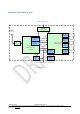
SPBT3.0DP1 Module Block Diagram Battery or External Supply SPBT 3.0DP1 Bluetooth Audio Module 1.8V Integrated Voltage Regulator INTERNAL RF antenna 1.8V 1.8V RF Filter & BALUN Host Controller interface HCI SPI PCM / I2S AUDIO INTERFACE PCM / I2S Bluetooth RADIO & AUDIO Coprocessor STLC2690 ARM Cortex MCU STM32F411CEY6 26.000 MHz I2S AUDIO INTERFACE I2S GPIO user interface GPIO UART user interface UART RESET BOOT0 BOOT1,etc. SYSTEM 32.768 kHz Internal / Ext. 32.768 kHz clock 1.8V 32.
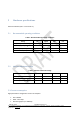
5 Hardware specifications General conditions (VIN = 3.3 V and 25 °C). 5.1 Recommended operating conditions Table 1: Recommended operating conditions 5.2 Rating Min. Typical Max. Unit Operating temperature range -40 - + 85 °C Supply voltage VIN 2.1 3.3 3.6 V Signal pin voltage - 1.8 - V RF frequency 2402 - 2480 MHz Absolute maximum ratings Table 2: Absolute maximum ratings Rating Min. Typical Max. Unit Storage temperature range -40 - + 85 °C Supply voltage, V IN -0.
Temperature: 25 °C Table 3: High Performance Power Consumption Modes (typical power consumption) Average Unit No connection, Page/Inquiry Scan, internal crystal LPO, Deep Sleep Mode 1.34 mA No connection, Page/Inquiry Scan, no external LPO, Active Mode 6.9 mA No connection, Page/Inquiry Scan, with external LPO, Active Mode 5.4 7.85 mA No connection, No Page/Inquiry Scan, no external LPO, Active Mode 7.65 mA Connection, no data traffic, Master 11.
5 GPIO_10 General purpose I/O or I2C_SDA line for MFI chip I/O 5V tolerant 6 TXD Transmit Data O 5V tolerant 7 GPIO_9 General purpose I/O I/O 5V tolerant 8 RXD Receive Data I 5V tolerant 9 CTS Clear to send (active low) I 5V tolerant 10 RTS Request to send (active low) I 5V tolerant 11 GPIO_11 I/O 5V tolerant 12 GPIO_12 I/O 5V tolerant 13 GPIO_7 General purpose I/O or I2C_SCL line for MFI chip General purpose I/O or I2C_SDA line for MFI chip General purpose I/O I/O
5.5 Mechanical dimensions Figure 4: mechanical dimensions January 2016 DocID0xxxxx Rev 0.17 This is preliminary information on a new product now in development or undergoing evaluation. Details are subject to change without notice. www.st.
Figure 5: Recommend land pattern top view 6 Hardware design SPBT3.0DP1 module with DP command embedded FW supports UART, I2C and GPIO hardware interfaces. Note: o o o o All unused pins should be left floating; do not ground. All GND pins must be well grounded. The area around the module should be free of any ground planes, power planes, trace routings, or metal for 6 mm from the module antenna position, in all directions. Traces should not be routed underneath the module. 6.
Here following some suggestions for the temperature profile based on the following recommendations. Table 5: Soldering Profile feature PB-free assembly Average ramp-up rate (TSMAX to TP) 3 °C/sec max Preheat: – Temperature min. (TS min.) – Temperature max. (TS max.) – Time (ts min. to ts max.
6.2 UART interface The UART is compatible with the 16550 industry standard. Four signals are provided with the UART interface. The TXD and RXD pins are used for data while the CTS and RTS pins are used for flow control. Host Bluetooth Module Figure 7: Connection to host device SPB323B-C Figure 8: Typical RS232 circuit January 2016 DocID0xxxxx Rev 0.17 This is preliminary information on a new product now in development or undergoing evaluation. Details are subject to change without notice. www.st.
SPBT3.0DP Hardware design 6.3 GPIO interface All GPIOs are capable of sinking and sourcing 4 mA of I/O current. Module GPIO configuration depends on the FW embedded.
SPBT3.0DP Hardware design 6.4.2 Internal reset circuit Note: o o RPU ranges from 30 kOhm 50 kOhm internally Rrst should be from 1KOhm to 10KOhm January 2016 DocID0xxxxx Rev 0.17 This is preliminary information on a new product now in development or undergoing evaluation. Details are subject to change without notice. www.st.
7 Regulatory compliance 7.1 FCC certification This module has been tested and found to comply with the FCC part 15 rules. These limits are designed to provide reasonable protection against harmful interference in approved installations. This equipment generates, uses, and can radiate radio frequency energy and, if not installed and used in accordance with the instructions, may cause harmful interference to radio communications.
7.1.2 Product manual instructions This section applies to OEM final products containing the SPBT3.0DP1 module, subject to FCC compliance. The final product manual must contain the following statement (or a similar statement that conveys the same meaning): Warning: Changes or modifications not expressly approved by the party responsible for compliance could void the user's authority to operate the equipment. (Part. 15.
7.2 IC certification The SPBT3.0DP1 module has been tested and found compliant with the IC RSS-247 rules. These limits are designed to provide reasonable protection against harmful interference in approved installations. This equipment generates, uses, and can radiate radio frequency energy and, if not installed and used in accordance with the instructions, may cause harmful interference to radio communications. However, there is no guarantee that interference may not occur in a particular installation.
7.2.2 Product manual instructions This section applies to OEM final products containing the SPBT3.0DP1 module, subject to IC compliance. The final product manual must contain the following statement (or a similar statement that conveys the same meaning): Warning: Changes or modifications not expressly approved by the party responsible for compliance could void the user's authority to operate the equipment.
7.3 Bluetooth certification Module with embedded stack and profile has been qualified according to SIG qualification rules: – – – – Bluetooth SIG Declaration ID: zzzzzz Product type: End Product Core spec version: 3.0 Product descriptions: Bluetooth module, spec V3.0 7.
8 Traceability Each module is univocally identified by serial number stored in a 2D data matrix laser marked on the bottom side of the module itself. The serial number has the following format: WW YY D FF NNN Table 6: Traceability information Letter Meaning WW week YY year D Product ID number FF Production panel coordinate identification NN Progressive serial number Each module bulk is identified by a bulk ID. BULK ID and module 2D data matrix are linked by a reciprocal traceability link.
9 Ordering information Table 7: Ordering information Order code SPBT3.0DP1 January 2016 Description Class 1 OEM Bluetooth Antenna Module Packing TBD MOQ pcs DocID0xxxxx Rev 0.17 This is preliminary information on a new product now in development or undergoing evaluation. Details are subject to change without notice. www.st.
Regulatory compliance 10 SPBT3.0DP1 Revision history Table 8: Document revision history Date 12-April-2016 January 2016 Revision 0.1 Changes First release DocID0xxxxx Rev 0.17 This is preliminary information on a new product now in development or undergoing evaluation. Details are subject to change without notice. www.st.
Regulatory compliance SPBT3.0DP1 Déclaration de conformité A.1 Certification FCC Le module SPBT3.0DP1 a été testé et déclaré conforme avec la section 15 de la Règlementation FCC. Ces limitations sont stipulées afin de procurer une protection raisonnable contre les interférences gênantes dans les installations approuvées.
Regulatory compliance A.1.1 SPBT3.0DP1 Instructions d'étiquetage Lors de l'intégration du module SPBT3.0DP1 dans le produit final, le fabricant doit s’assurer que les exigences en matière d'étiquetage de la FCC sont satisfaites . Une déclaration doit être placée sur l’étiquette extérieure du produit final indiquant que le produit comprend un module certifié.
A.1.2 Instructions pour l’utilisation du produit La présente section concerne les produits finis contenant le module SPBT3.0DP1, assujettis aux normes FCC. Le manuel du produit final doit contenir la déclaration suivante (ou une mention analogue que recouvre la même notion): “ Avertissement: Les changements ou modifications non expressément approuvés par la partie responsable de la conformité pourraient annuler l'autorisation de l'utilisateur de faire fonctionner cet équipement. (Section 15.
A.2 Certification IC (a) Le module SPBT3.0DP1 a été testé et déclaré conforme avec la Règlementation IC CNR-210. Ces limitations sont stipulées afin de procurer une protection raisonnable contre les interférences gênantes en installations approuvées. Cet appareil génère, utilise et diffuse des ondes radio et, s’il n’est pas installé et utilisé en conformité avec les instructions dont il fait l’objet, peut causer des interférences gênantes sur les communications radio.
A.2.1 Instructions d'étiquetage Lors de l'intégration du module SPBT3.0DP1 dans le produit final, le fabricant doit s’assurer que les exigences en matière d'étiquetage de la IC sont satisfaites . Une déclaration doit être placée sur l’étiquette extérieure du produit final indiquant que le produit comprend un module certifié.
Ces limites sont conçues pour fournir une protection raisonnable contre toute interférence dangereuse issue d'une installation résidentielle. Cet équipement produit, utilise et peut émettre de l'énergie radio électrique et, s'il n'est pas installé et utilisé conformément aux présentes instructions, peut causer des interférences nuisibles aux communications radio. Cependant, il se peut que des interférences se produisent dans une installation particulière.
A.3 Certification CE Le module SPBT3.0DP1 a obtenu une certification de conformité aux normes suivantes: – EN 300 328 V1.8.1 :2012 – EN 300 328 V1.9.1 :2015 – EN 301 489-17 V2.2.1 :2009 – EN 301 489-1 V1.9.2:2011 – EN 62479 :2010 – EN60950-1:2006 + A11:2009 + A1:2010 + A12:2011 + A2 :2013 Le module est certifié CE: January 2016 DocID0xxxxx Rev 0.17 This is preliminary information on a new product now in development or undergoing evaluation. Details are subject to change without notice. www.
IMPORTANT NOTICE - PLEASE READ CAREFULLY: STMicroelectronics NV and its subsidiaries (“ST”) reserve the right to make changes, corrections, enhancements, modifications, and improvements to ST products and/or to this document at any time without notice. Purchasers should obtain the latest relevant information on ST products before placing orders.