
User's Manual


January
2016 DocID0xxxxx Rev 0.17
This is preliminary information on a new product now in development or undergoing evaluation. Details are subject to change
without notice. www.st.com
List of tables
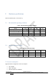
Table 1: Recommended operating conditions ................................................................................... 9
Table 2: Absolute maximum ratings ..................................................................................................... 9
Table 3: High Performance Power Consumption ............................................................................ 10
Table 4: Pin assignment ......................................................................................................................... 10
Table 5: Soldering .................................................................................................................................... 14
Table 6: Traceability information ......................................................................................................... 23
Table 7: Ordering information .............................................................................................................. 24
Table 8: Document revision history .................................................................................................... 25
List of figures
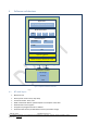
Figure 1: Software Architecture Overview ..................................................................................................... 6
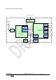
Figure 2: Block Diagram ................................................................................................................................ 8
Figure 3: Pin assignment ............................................................................................................................... 10
Figure 4: mechanical dimensions .................................................................................................................. 12
Figure 5: Recommend land pattern top view ................................................................................................ 13
Figure 6: Soldering profile ............................................................................................................................ 14
Figure 7: Connection to host device ............................................................................................................. 15
Figure 8: Typical RS232 circuit .................................................................................................................... 15
Figure 9: External reset circuit ...................................................................................................................... 16